Repair of 2001 Subaru Forester Sunroof Drive
© 2013Alan Dunwell
Problem:There is a known issue with the Subaru Forester Sunroof drive systems in that the drive cables are attached to the sliding glass assembly via some cheap plastic sections. Bad planning on their part to use a fragile plastic in an area that will get baked in high temperatures in the sun. To make matters worse, they do not sell replacement plastic parts. The plastic is attached to the cable, the cable is in the drive tube and that all mounts to the aluminum rack assembly. Naturally, Subaru will only sell the entire rack assembly if you need just the plastic bit. A quick price check was ~$750.00 just for the parts. I did check with some junkyards but everything they had was broken in the same way. Look for little white plastic bits in the track assembly, that means it is broken.
I should mention that if you have a later model Forester in the 2003-2005 range, there does seem to be a Tech Service Bulletin about a $20 repair kit that includes some small plastic bits that you insert from the top without having to remove the rack, etc. You can do a web search for "TSB 15-134-08R.zip" to download the 4-picture image of the bulletin which includes the part number of the kit. Whether this works or not is unknown to me. There is a discussion of the kit in the long merged thread on the Subaru Forester Owners Forum
http://www.subaruforester.org/vbulletin/f88/forester-moonroof-problems-merged-thread-3967/index38.html
starting with post #561. There was no response or reference to anyone who has actually tried the kit. You may want to read through all the pages there just to get a feel for the scope of the sunroof problems in general. This document deals primarily with the problem of the broken plastic where the drive cable attaches to the rear section of the glass slider drive section.
One more preliminary note here, my "fix" does a repair enough to get the drive system back together and into the closed position. It involves an epoxy glue-up repair and I don't trust that enough to actually use the drive after the fix was all done. You might be more comfortable with that if your's is not so broken as mine was.
Photo Journal of the process:
Normally, service manuals show you how to take something apart and then say "Assembly is the reverse of disassembly" or something like that. I didn't start taking pictures till I had the whole thing apart and cleaned up so in this case "Disassembly is the reverse of the shown assembly." We start off looking at the broken drive pieces and then do a pseudo-fix and a reassembly of the whole bother back into the vehicle. Not shown here is that all the pieces/parts were cleaned in solvent and air blow-dried. To see a photo in greater detail, click on that photo.
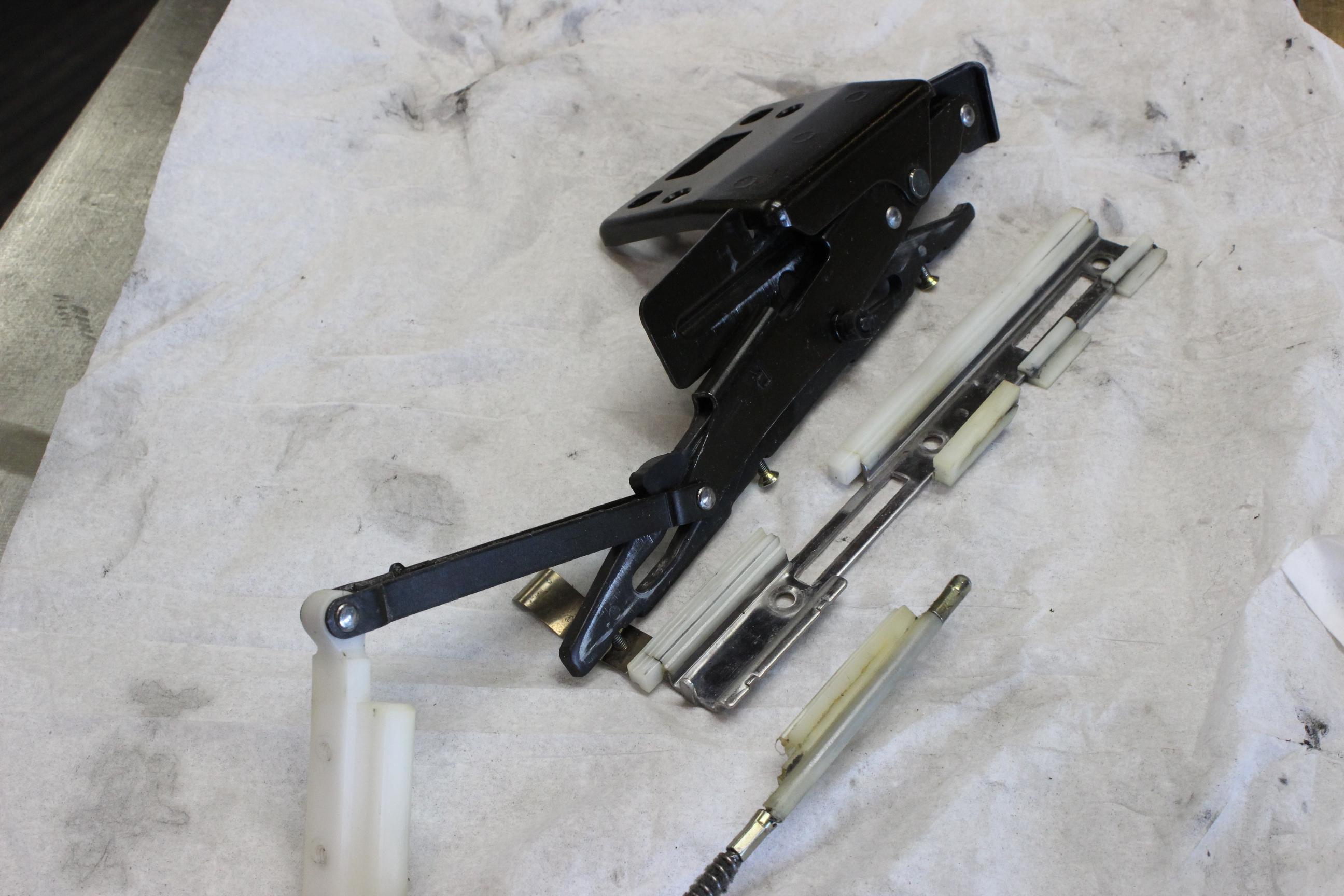
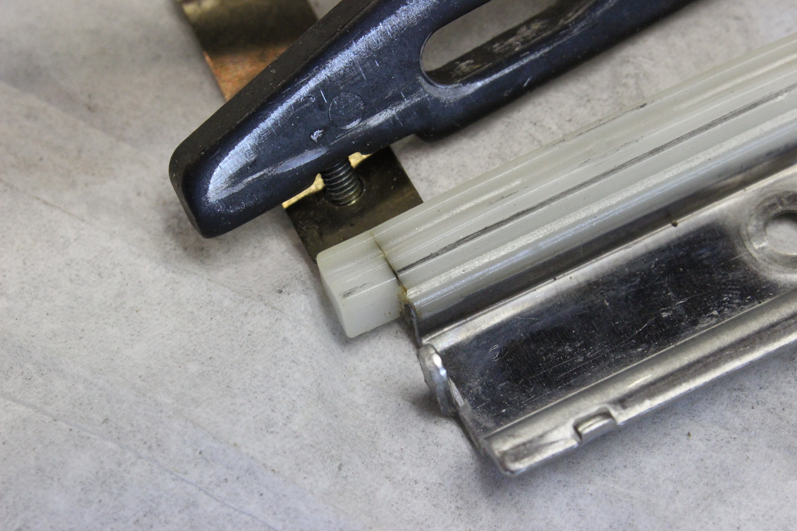
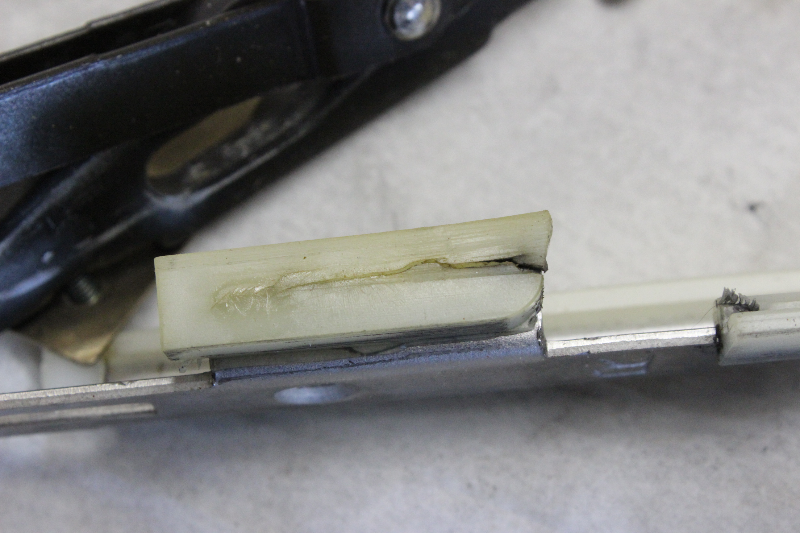
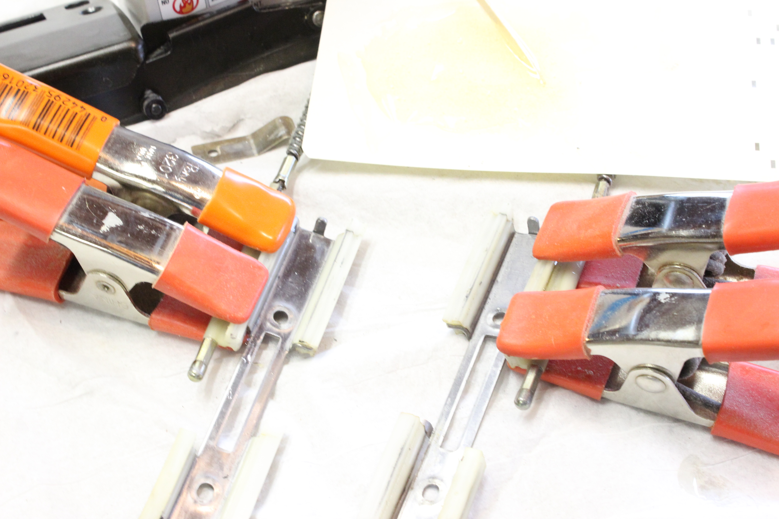
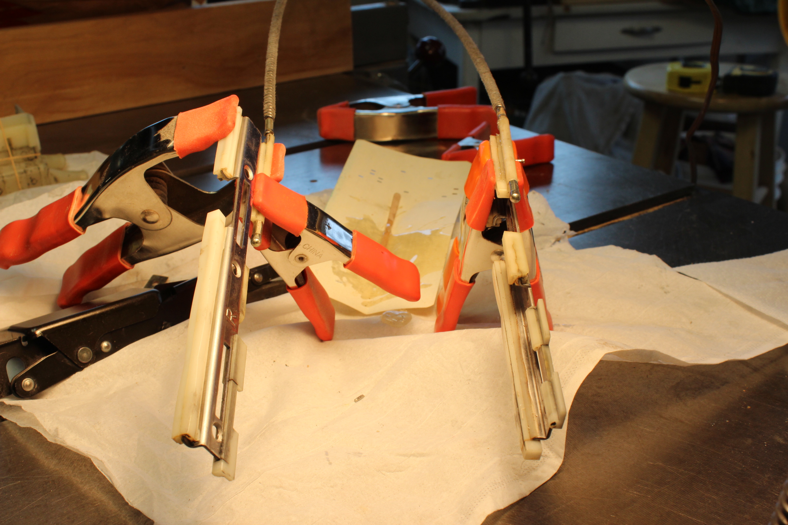
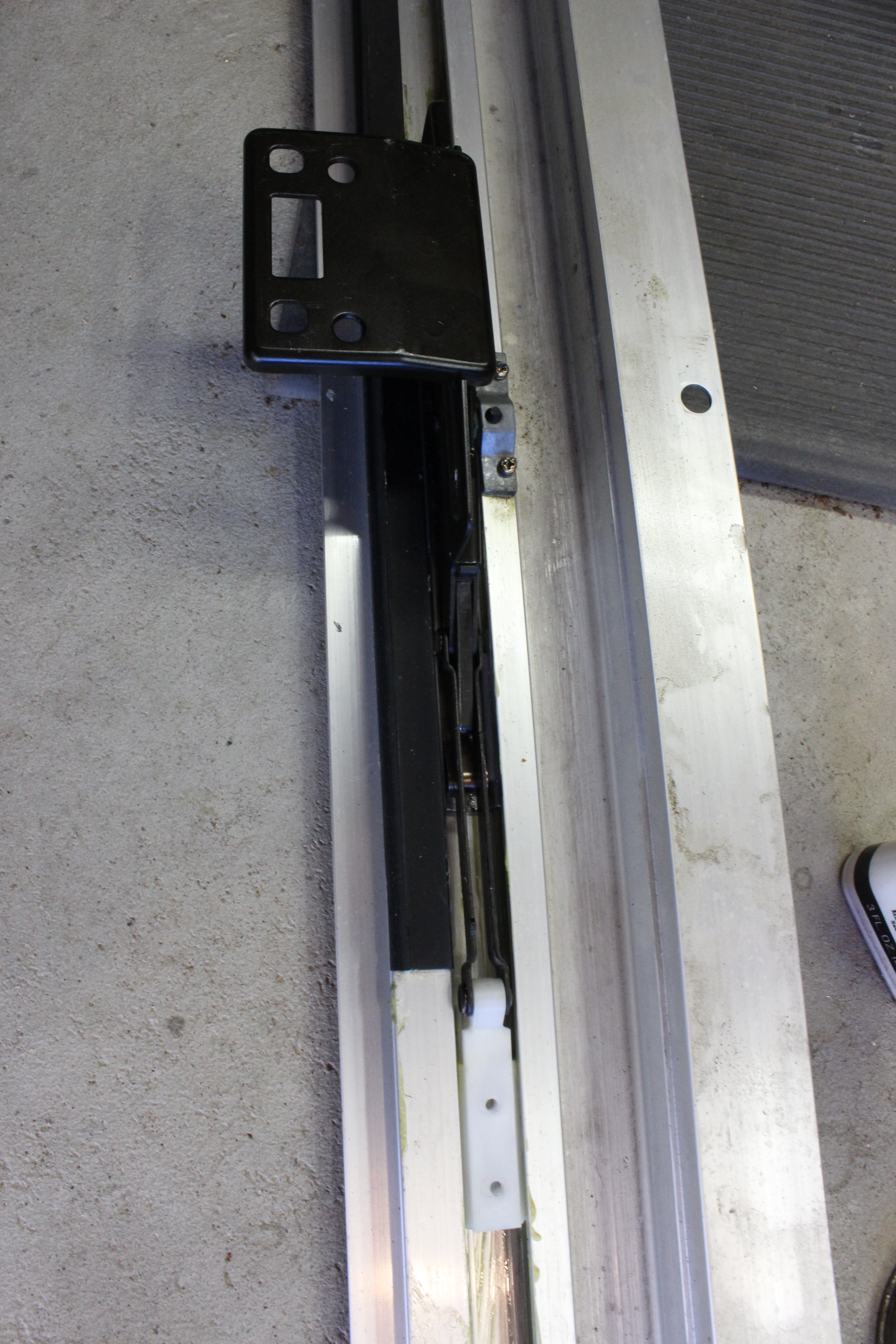
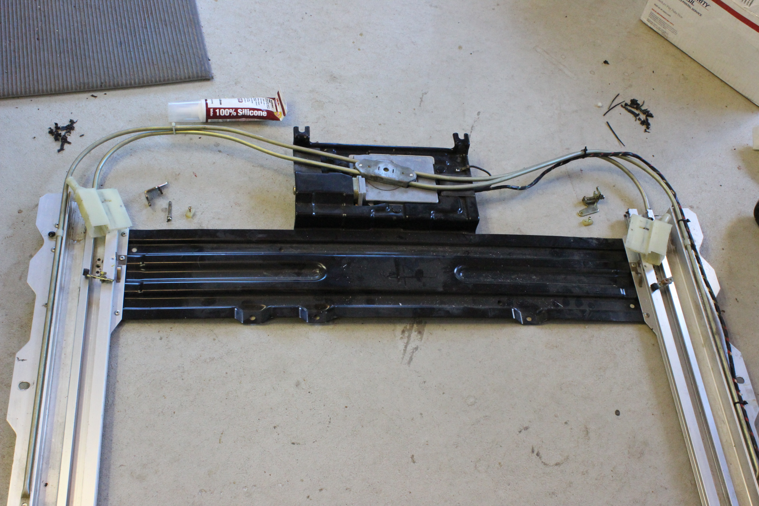
Here are the pieced of interest. The first photo shows the rear drive slider assembly, it is taken apart into three pieces, the metal doodad that slides and lifts and attaches to the glass. Attached with three small screws to the bottom of that is a sheet metal piece to which are attached the cheesy cheap plastic bits. Look at photo two and three to see how they degrade. If you find little squares of white plastic in your track they are the broken off end bits, photo two shows one about to go. The third part is the cable part of the drive. This is actually slid though the back outside plastic bit and then a bead is swaged onto the cable to hold it in place. This piece is actually supposed to be attached to the sheet metal part but you can see it has broken off. Thus it will sort of push forward and kind pull back when it snags on the trailing big white plastic piece, you can see that on the first metal part I mentioned. This tends to cant the two sides (L & R) differently and one will rise up and park while the other may or may not depending on it's condition.
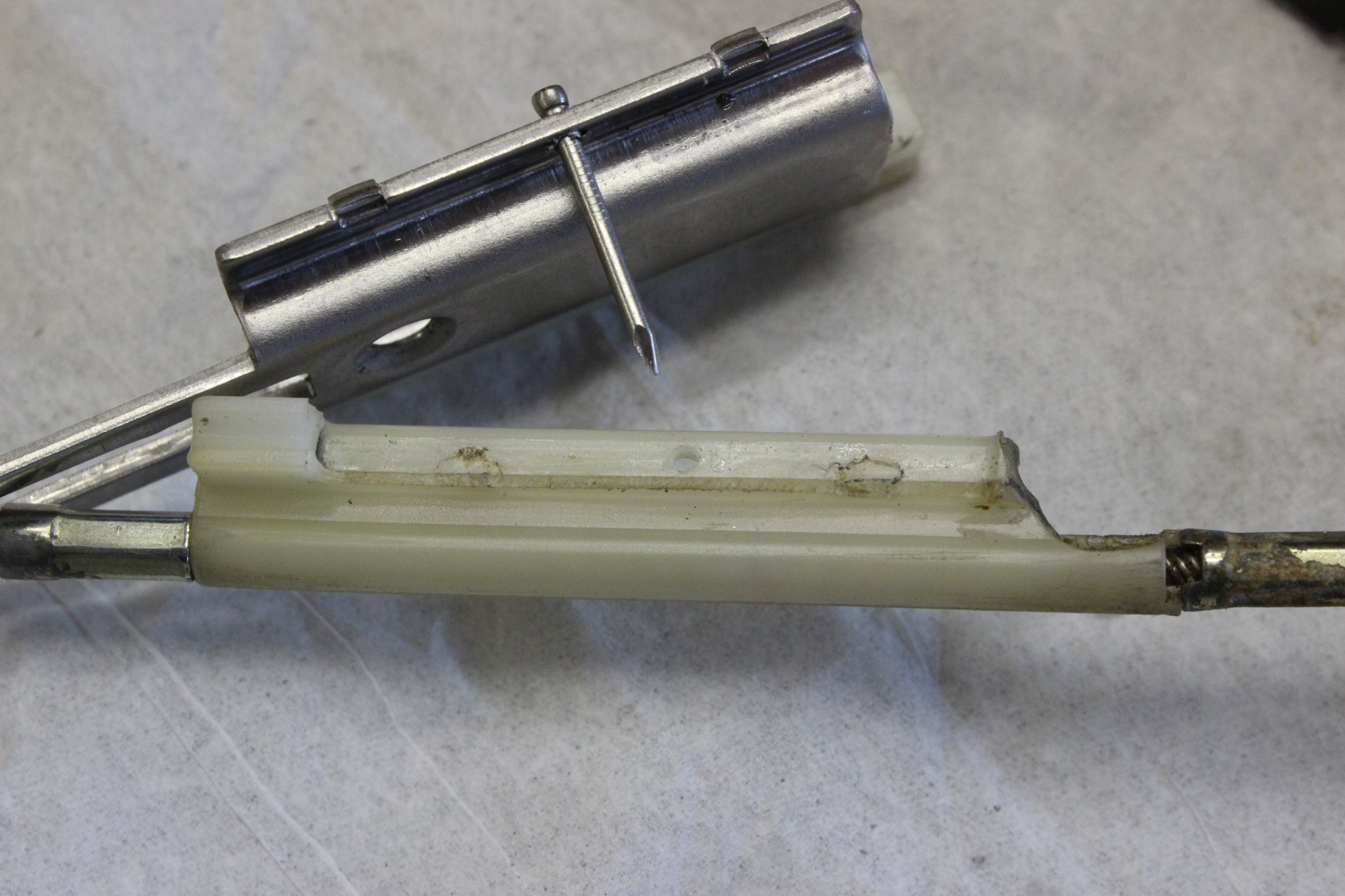
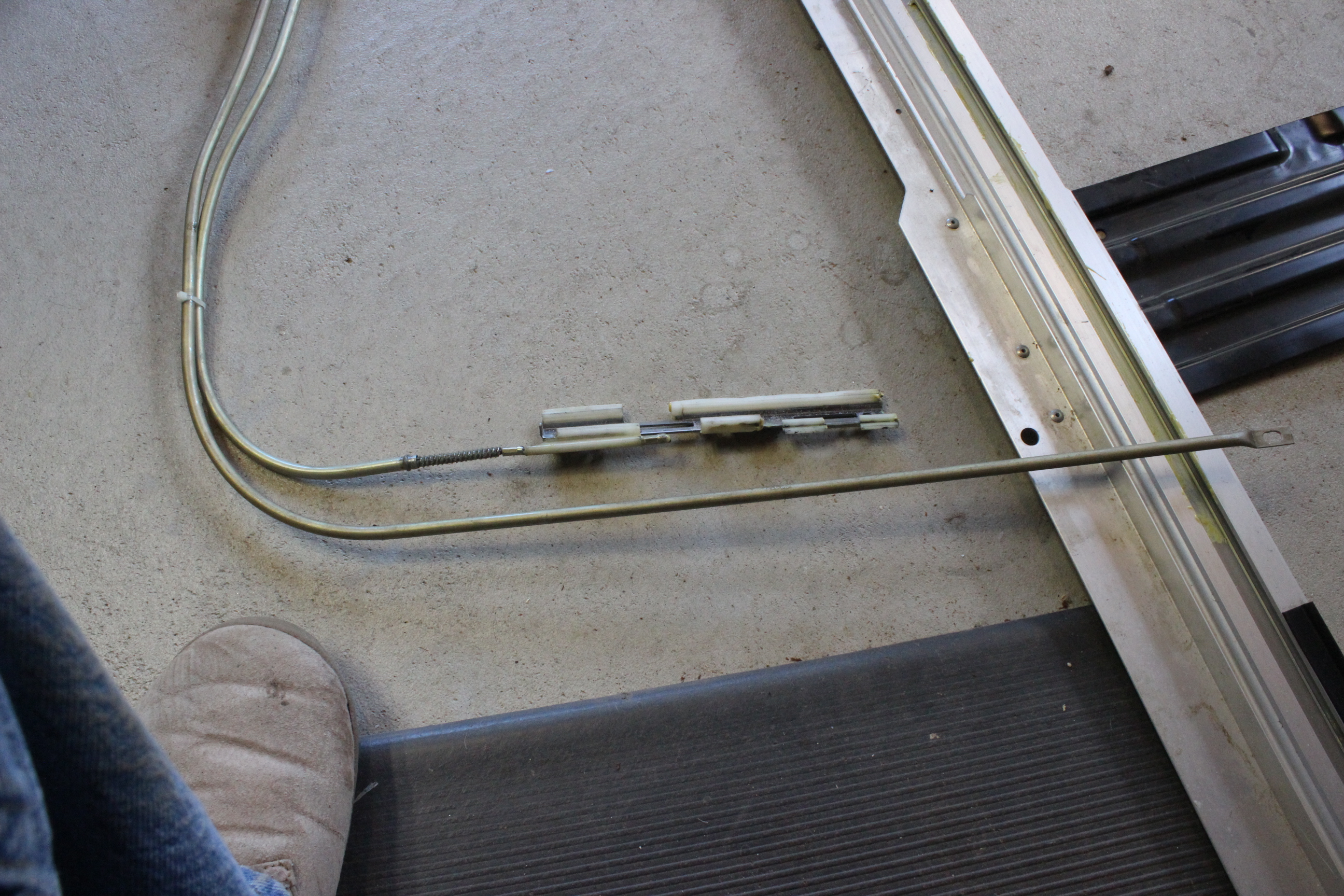
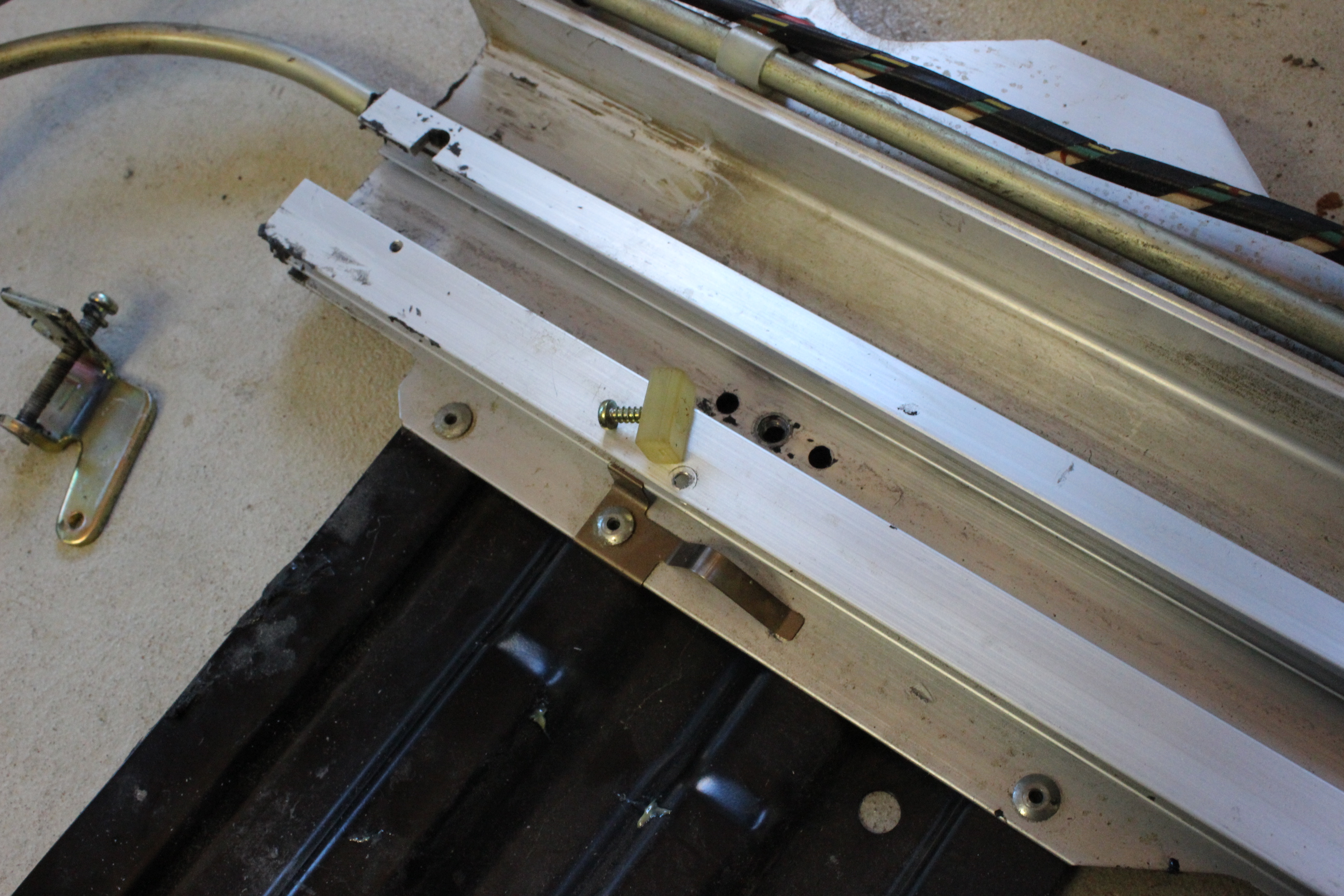
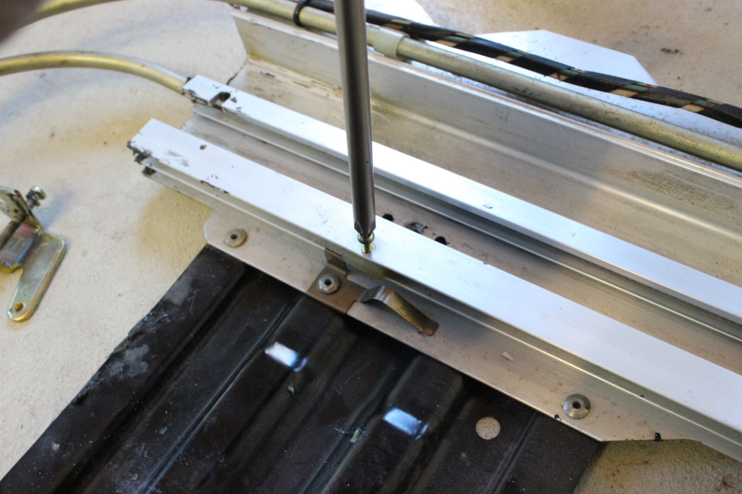
Here is a closer look at the broken bit and where it is supposed to attach to the sheet metal. You can see I drilled a #52 bit hole through the metal and then through the plastic to act as an alignment pin. I only needed to do this on one side where the plastic had broken into two pieces. On the other side it was just split and I was able to slip it back in place. I glued both sides with some 8-hour high strength epoxy (System Three T-88) and let it cure out over night. I then filed and smoothed out the epoxy to make it all nice and even. I left the pin in place and just clipped it off and filed flush. The last photo shows the fixed sheet metal assembly with the cable attached and slid back into the drive tube. I applied Lubraplate lithium grease all over the cable. Just for reference, the cable is actually just a big coil spring with some sort of fuzzy stuff up the inside. So the grease was soaked into the fuzzy stuff and slid in the tube quite easily.
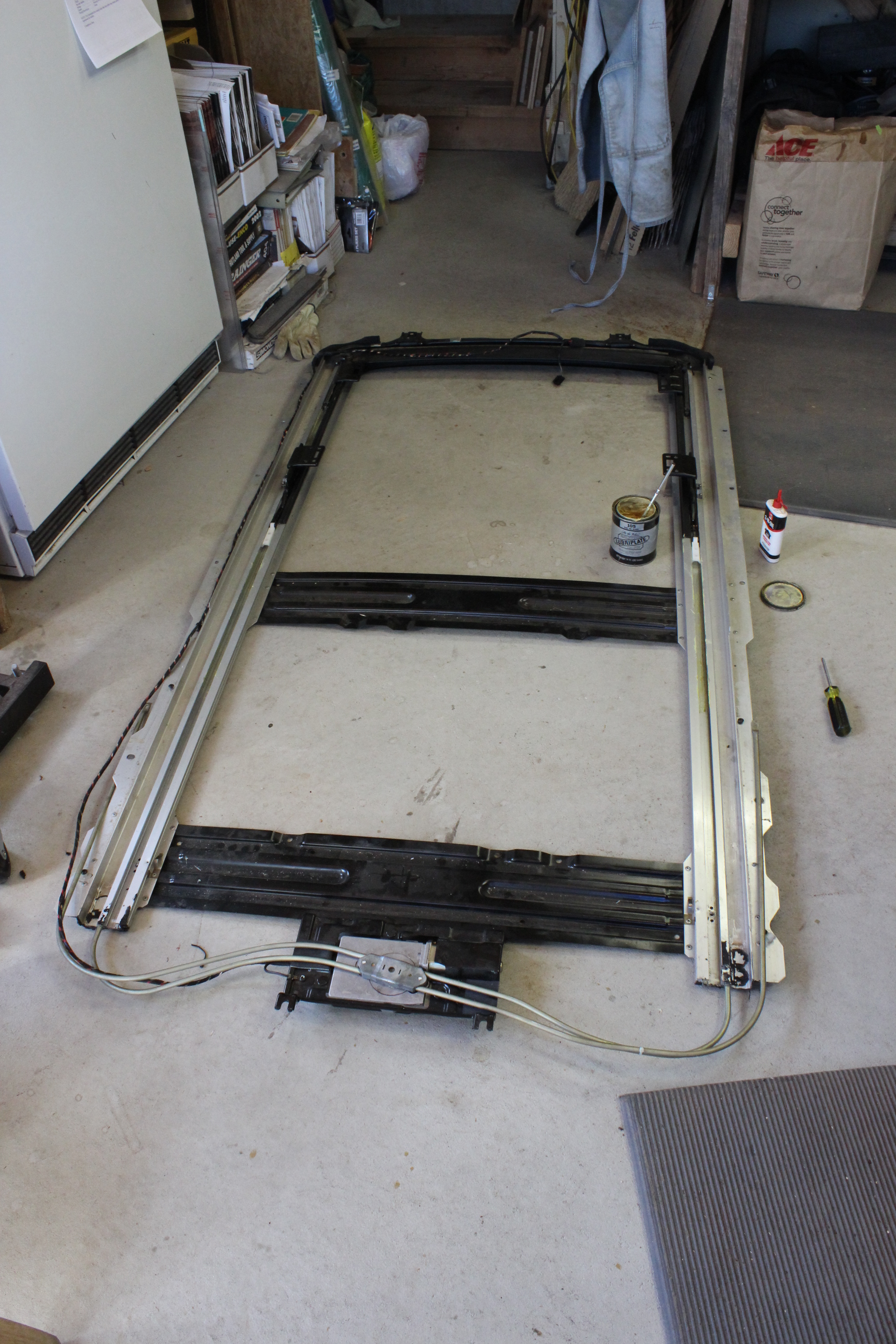
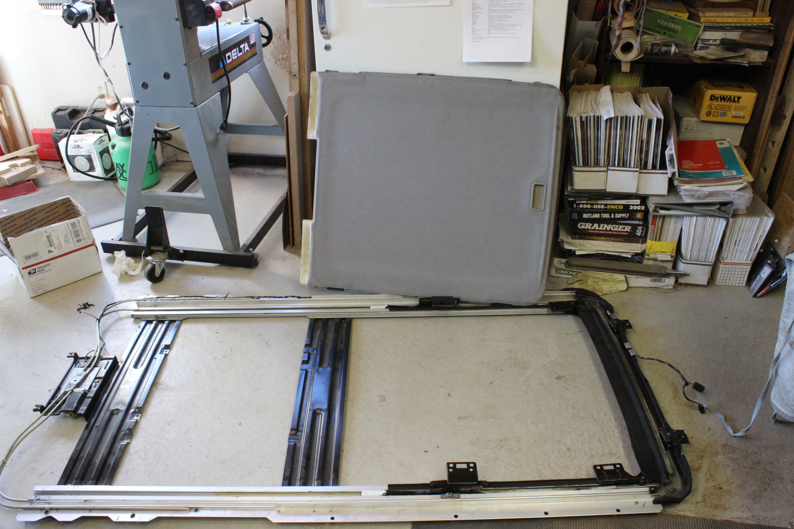
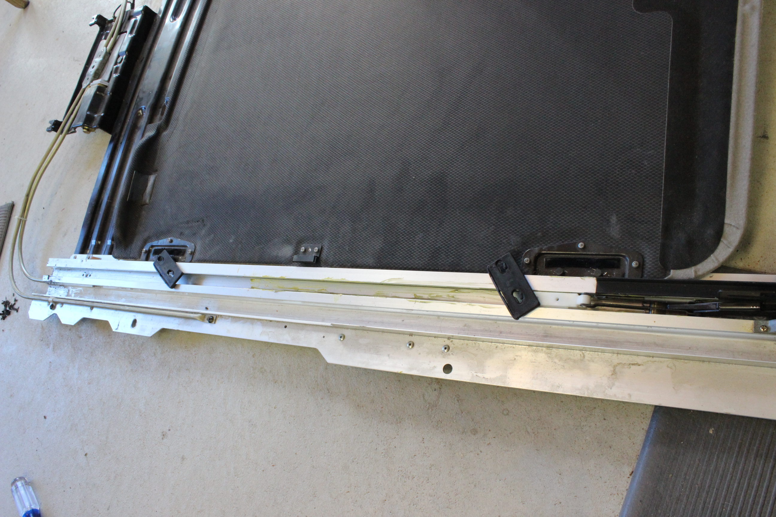
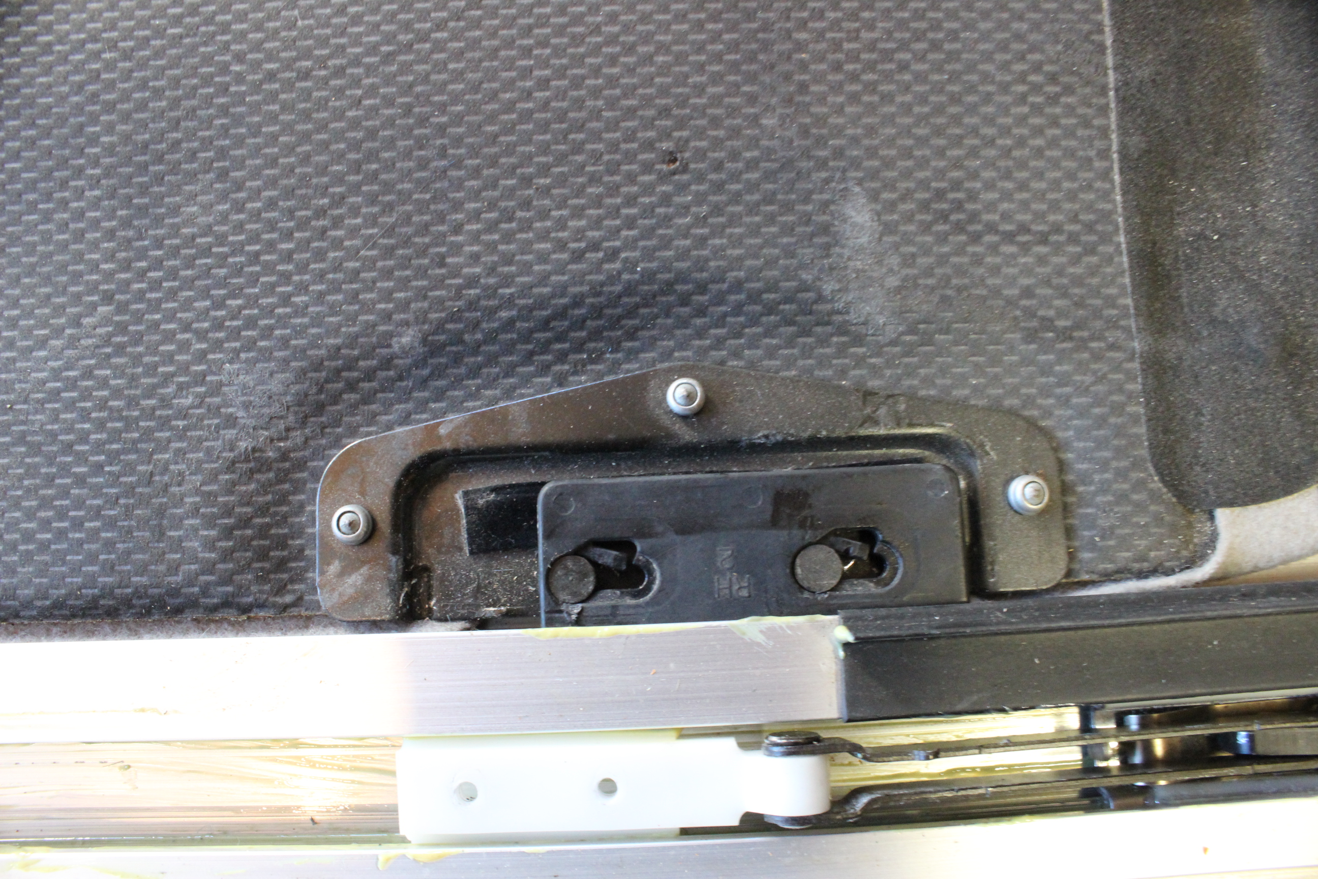
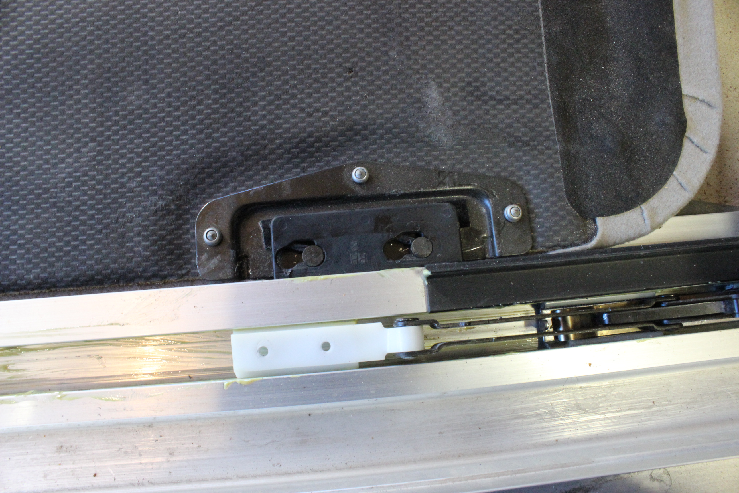
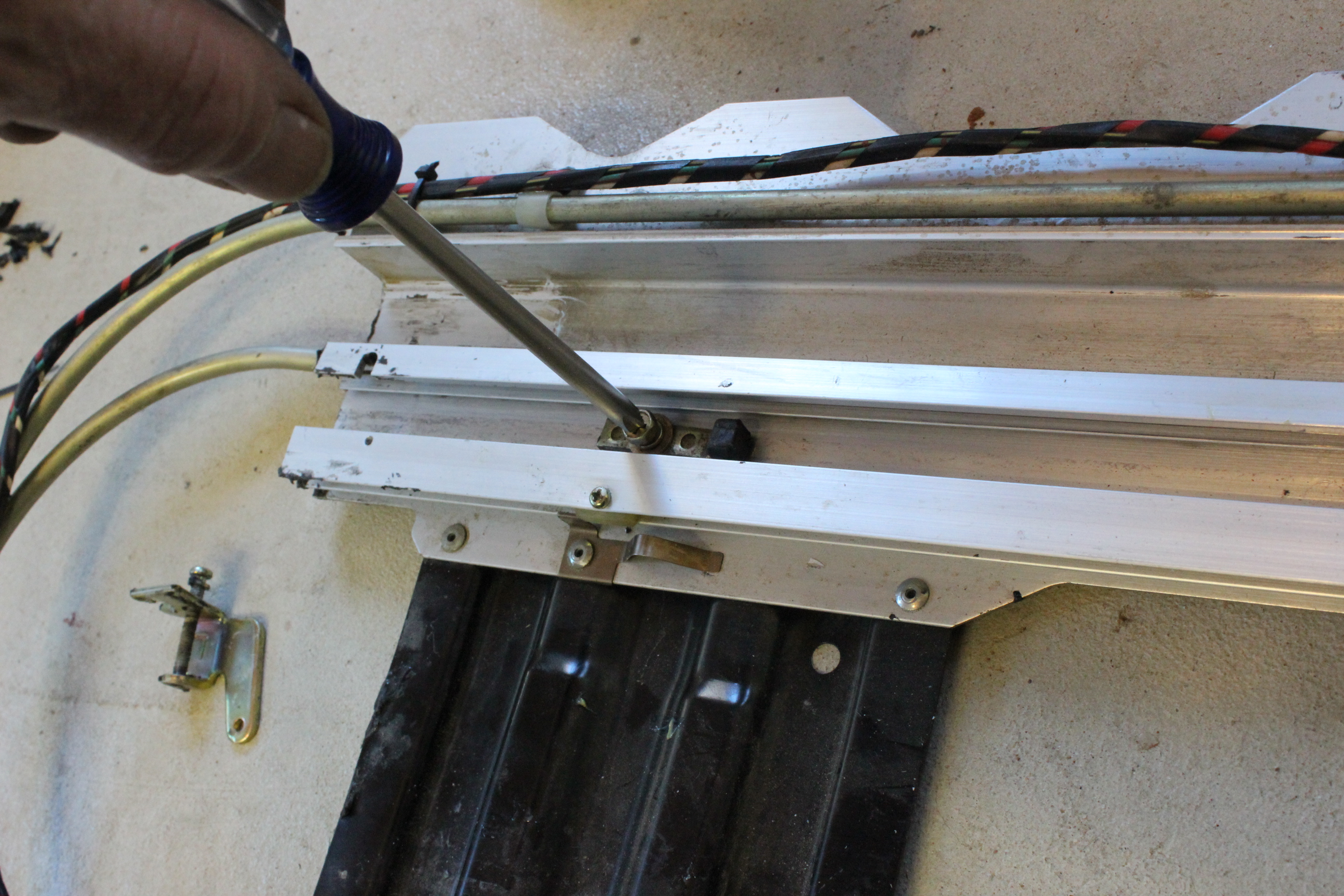
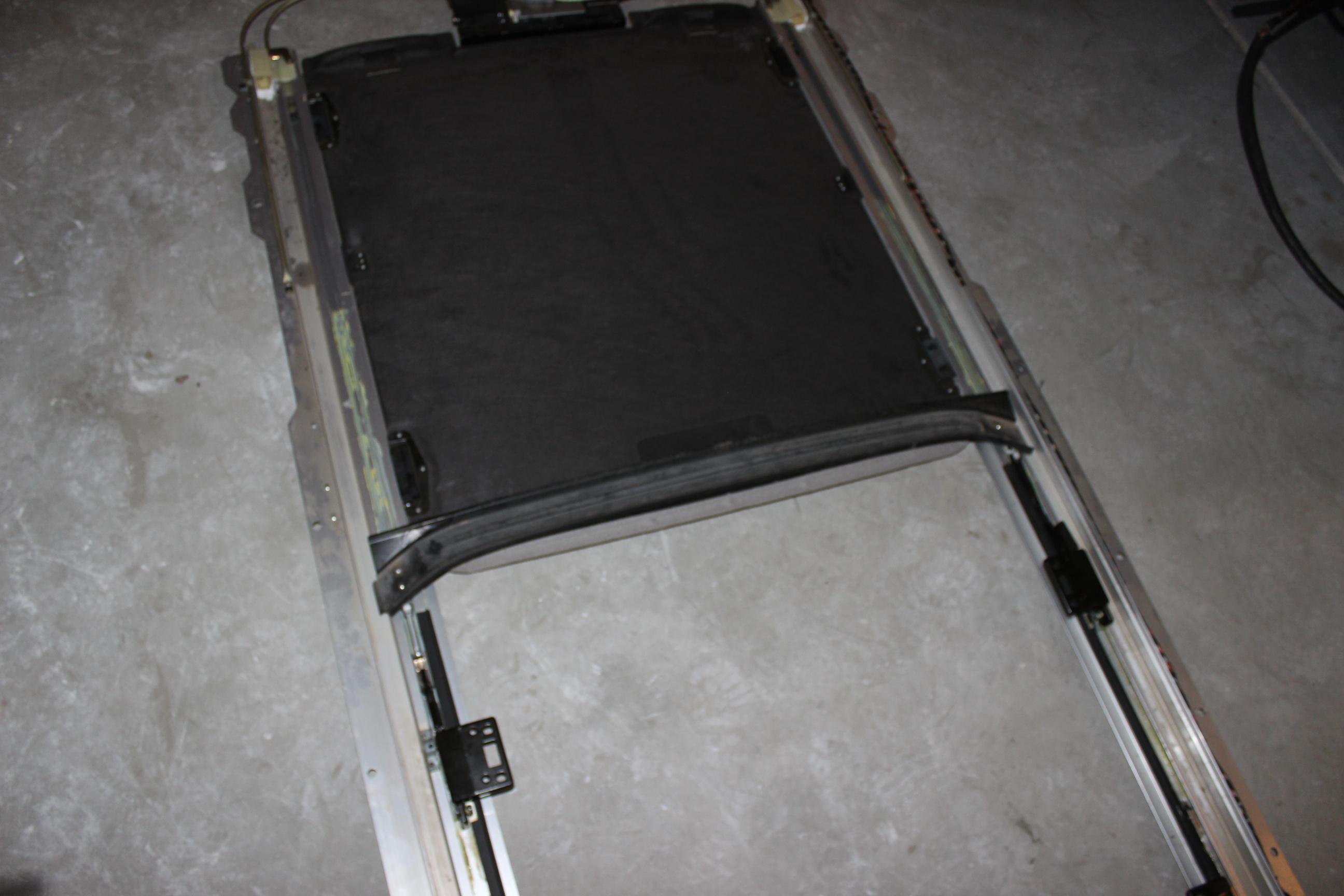
Here is a shot of the rack assembly and a close up of the slider assembly in the rack. Notice the can of Lubraplate grease and the brush. I goobered the slider assembly parts that move and track slots well with the grease. Also notice the forward sliders that press down the wind deflector, remember to lube those as well. Before I removed the assembly I ran the motor to the completely closed position. so the motor thought it was all the way forward. Here I slid the the sliders forward as far as they would go. Then you need to get a flat blade screwdriver or other push stick and press on the back end of the metal parts where the drive cable attaches. This is the center bottom bit of the slider assembly, not that trailing piece with the white plastic. Be careful not to press on the plastic piece that was repaired, only on the metal center piece. As you push this help lift the part that attaches to the glass to raise it up as far as it will go. This is the most forward position of the cable. Once it is all forward on both sides, go to the motor end and press the cable tube assembly down onto the motor drive gear. This will engage the cables spirals. Attach it with the two large screws to hold it in place.
Next the sliding cover goes in it's slot. I didn't grease this but left it dry. I can be just slid in the back end and flexed over the motor stuff, but I noticed that the slider pieces are "snap in" onto some pins. So I removed them from the slider when I was disassembling. It is a bit of a fuss with two flat blade screwdrivers. Now for assembly they just slip into the track, slide over the pins and then shift sideways to snap lock in place. You may only have one that slides this way, I noticed that one I had from the junkyard had three that slide cross-wise and one that slides sideways. Not sure why.
The next is to close up the track ends. First is the little plastic block that acts as a stop for the sliding cover. Then the stop in the main track
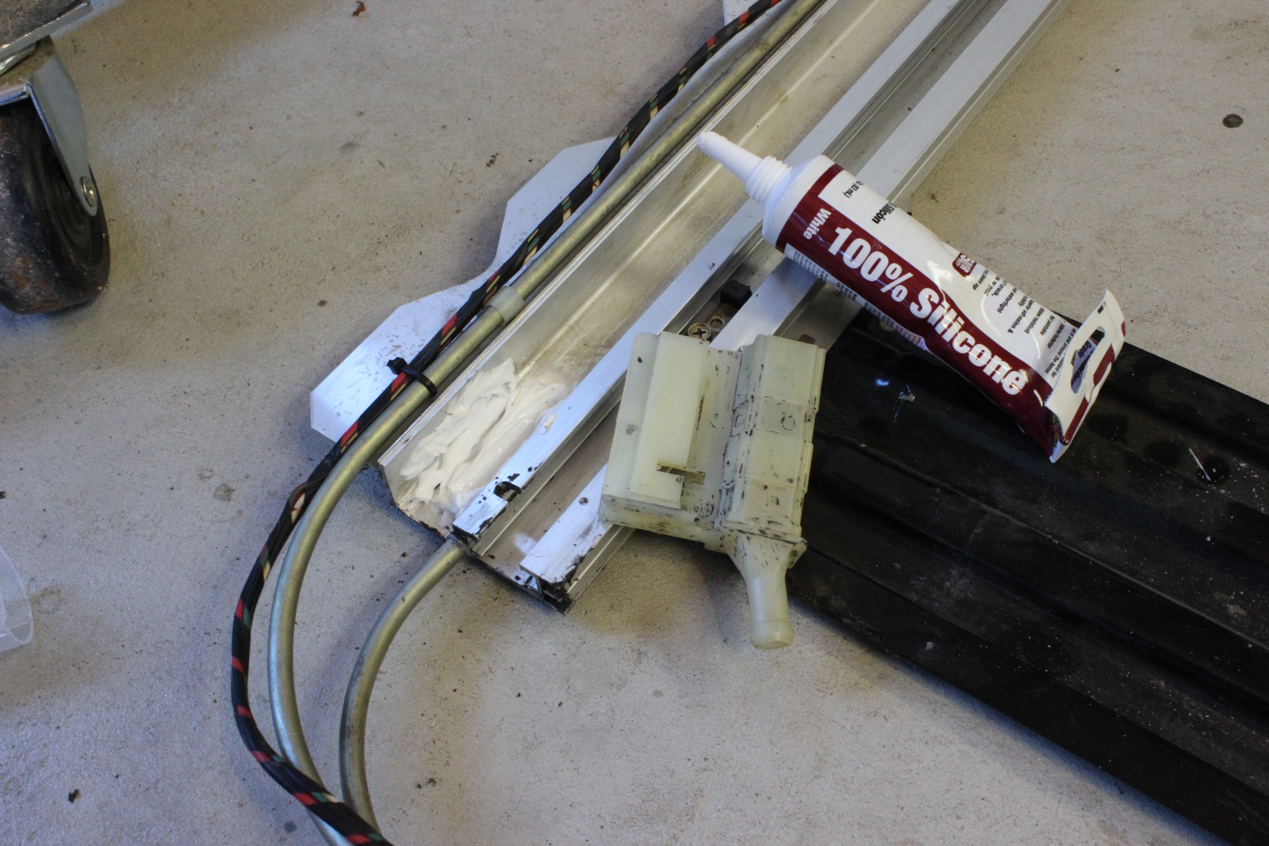

The last bit is to put in the plastic drain pieces. These also act as the lock for the cable tubes to the track. This needs to be water tight since any moisture that gets in is ducted to this part of the track and needs to drain out the hoses. So goober in a good bit of RTV type silicon rubber seal stuff. I also washed the plastic and track there with alcohol first to make sure I got any grease removed. Press the plastic in place and secure it with the metal bracket with two screws, one in the end and the other down into the track.
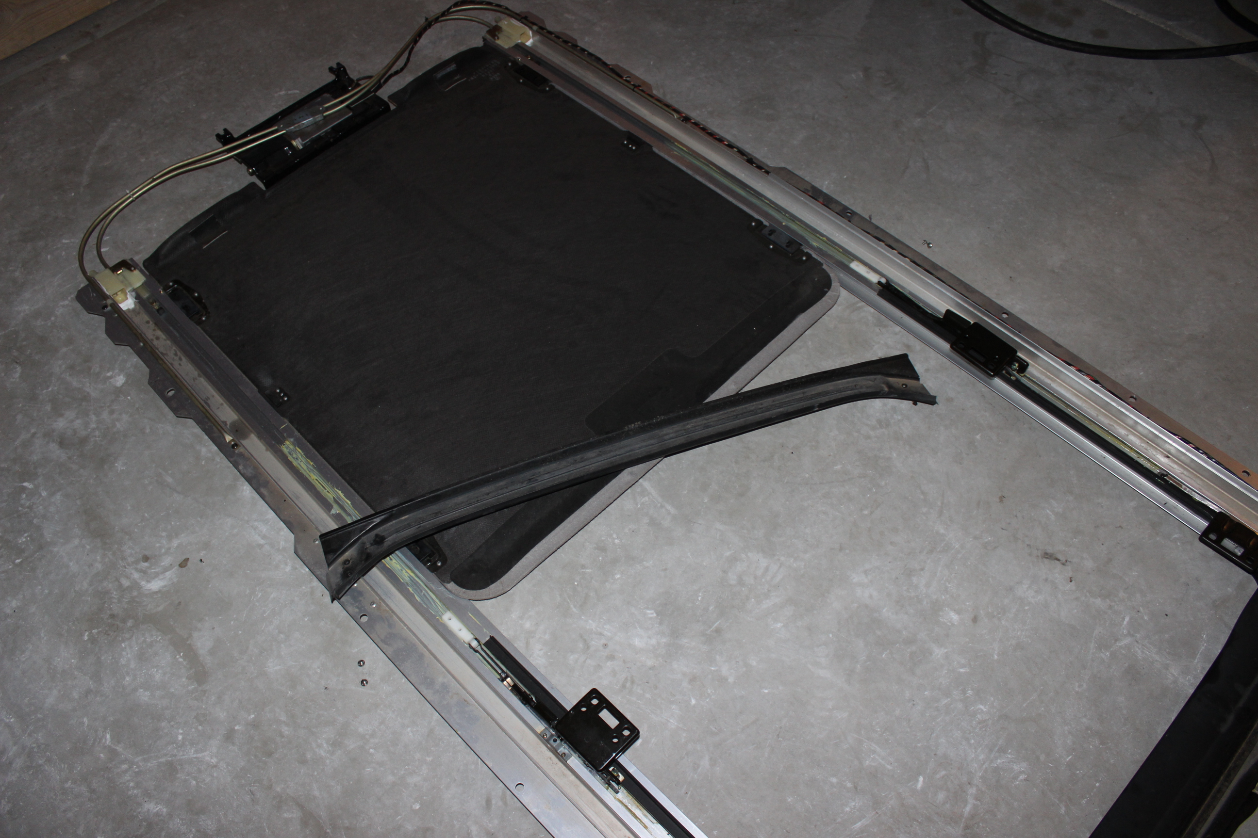
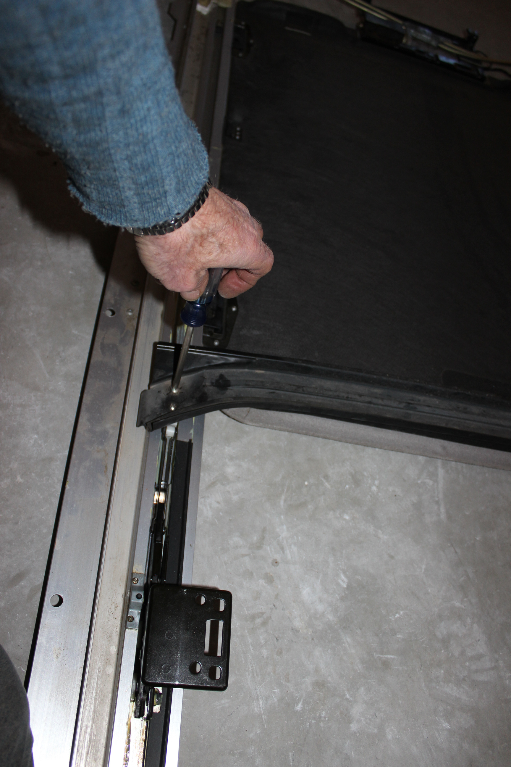
The last bit is to attach the cross piece between the two back sliders. This is actually mostly a drain to duct any moisture from the back of the window into the tracks on the sides.
That pretty much finishes the fix and prepares the track assembly, it is now ready to be re-installed into the car. A bunch of photos in order here without comments unless there is a trick or detail to note.
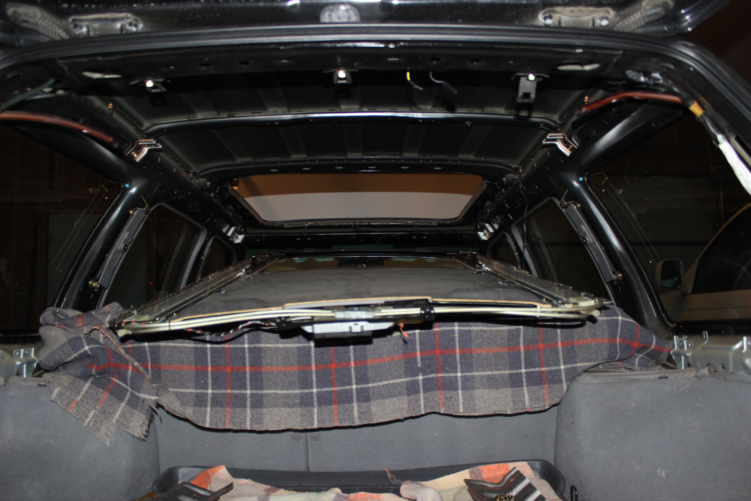
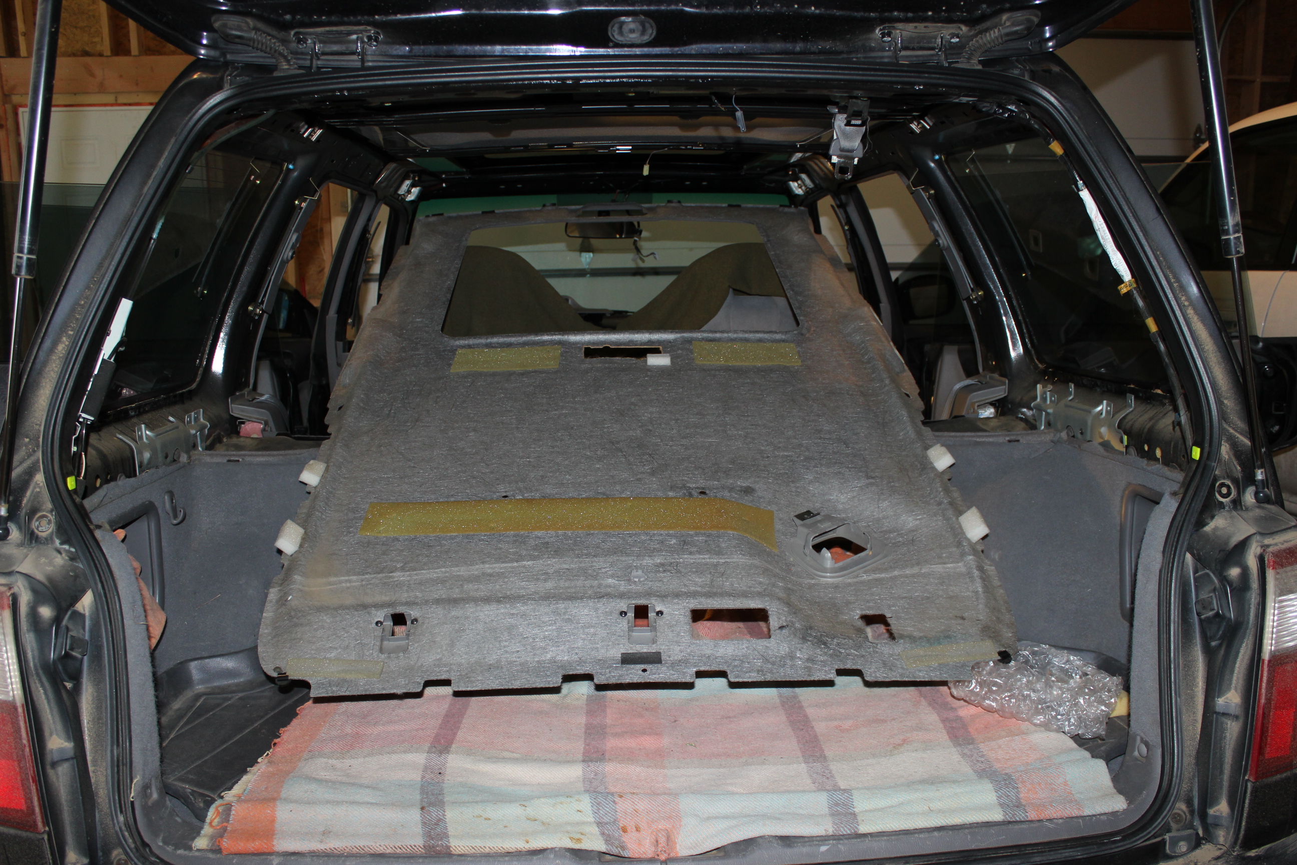
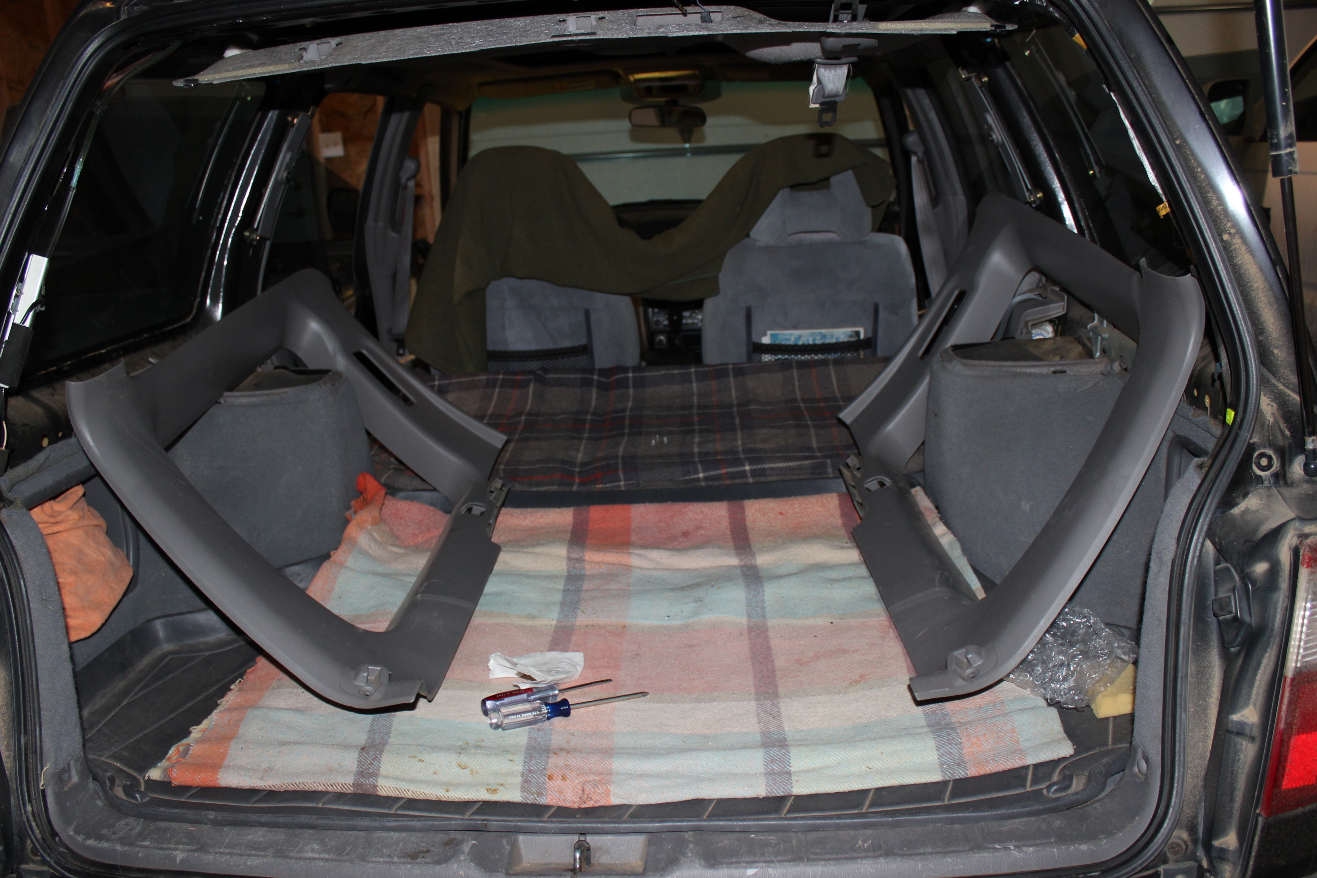
Be sure to protect the seats with something. I took off the rear seat head rests and laid the assembly ~ in place.
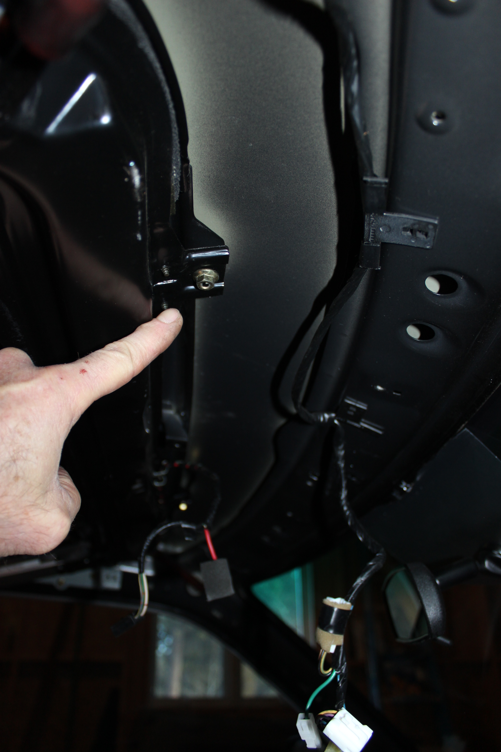
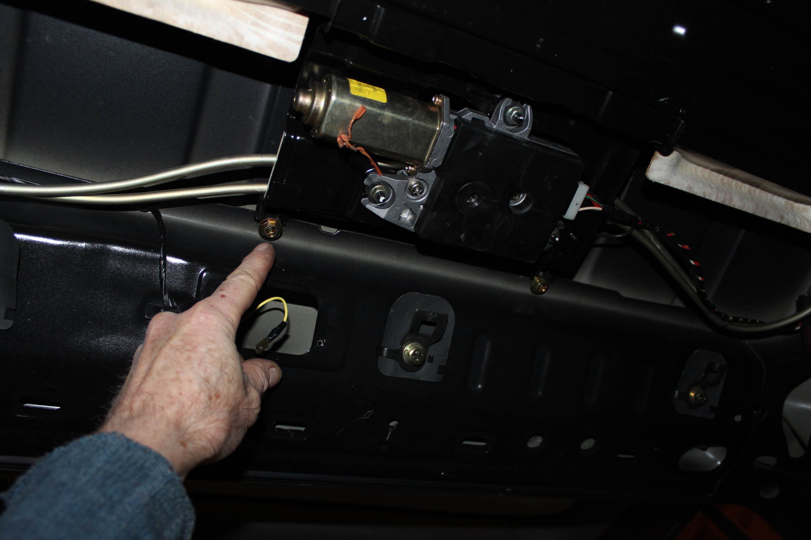
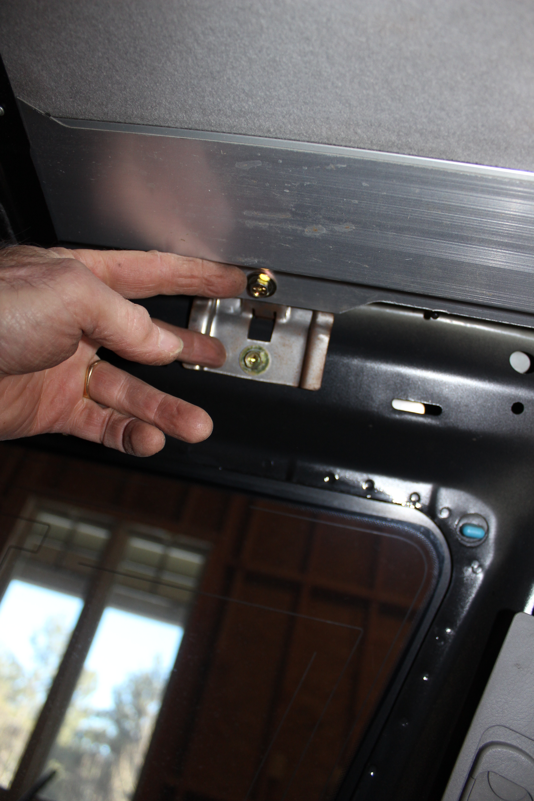
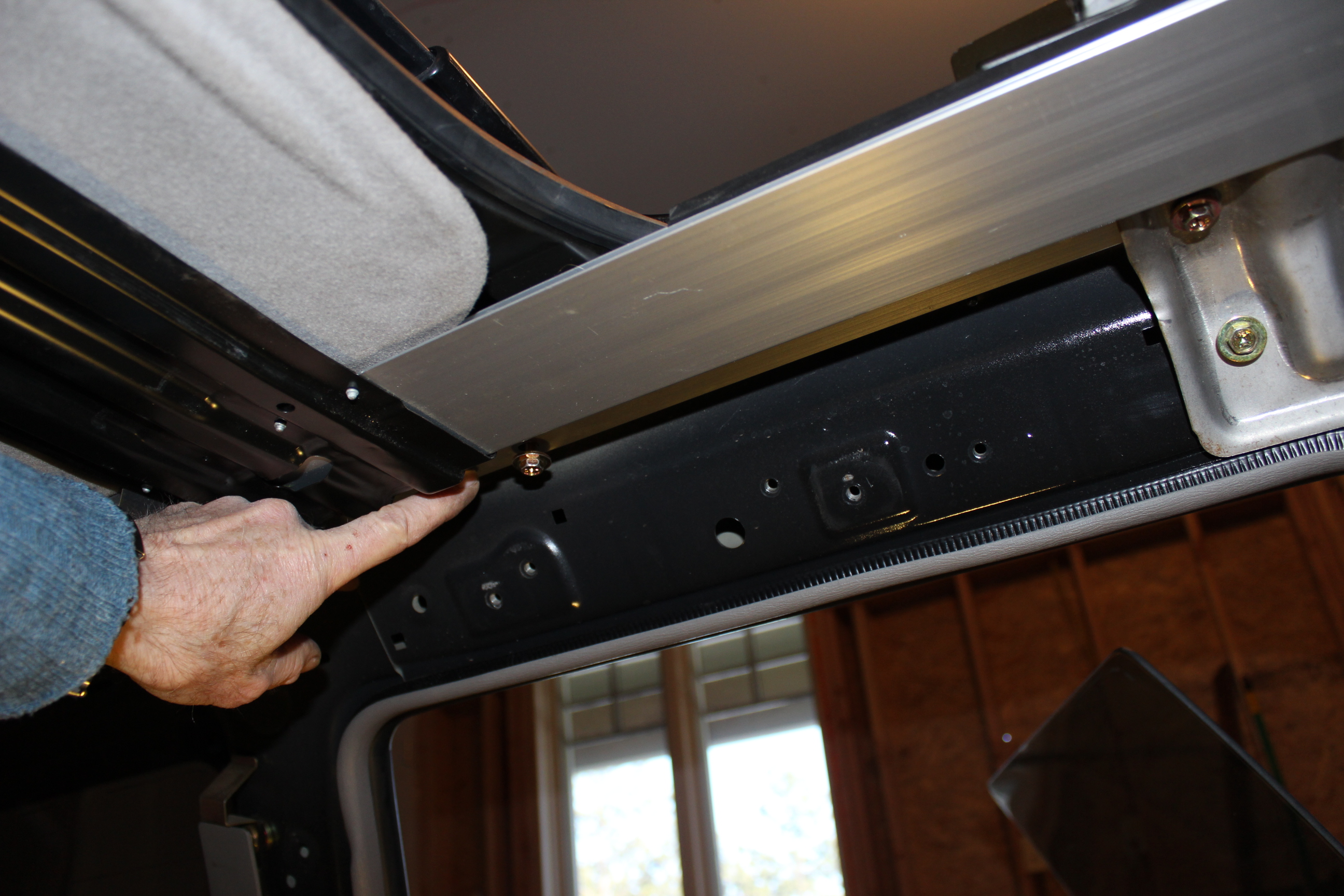
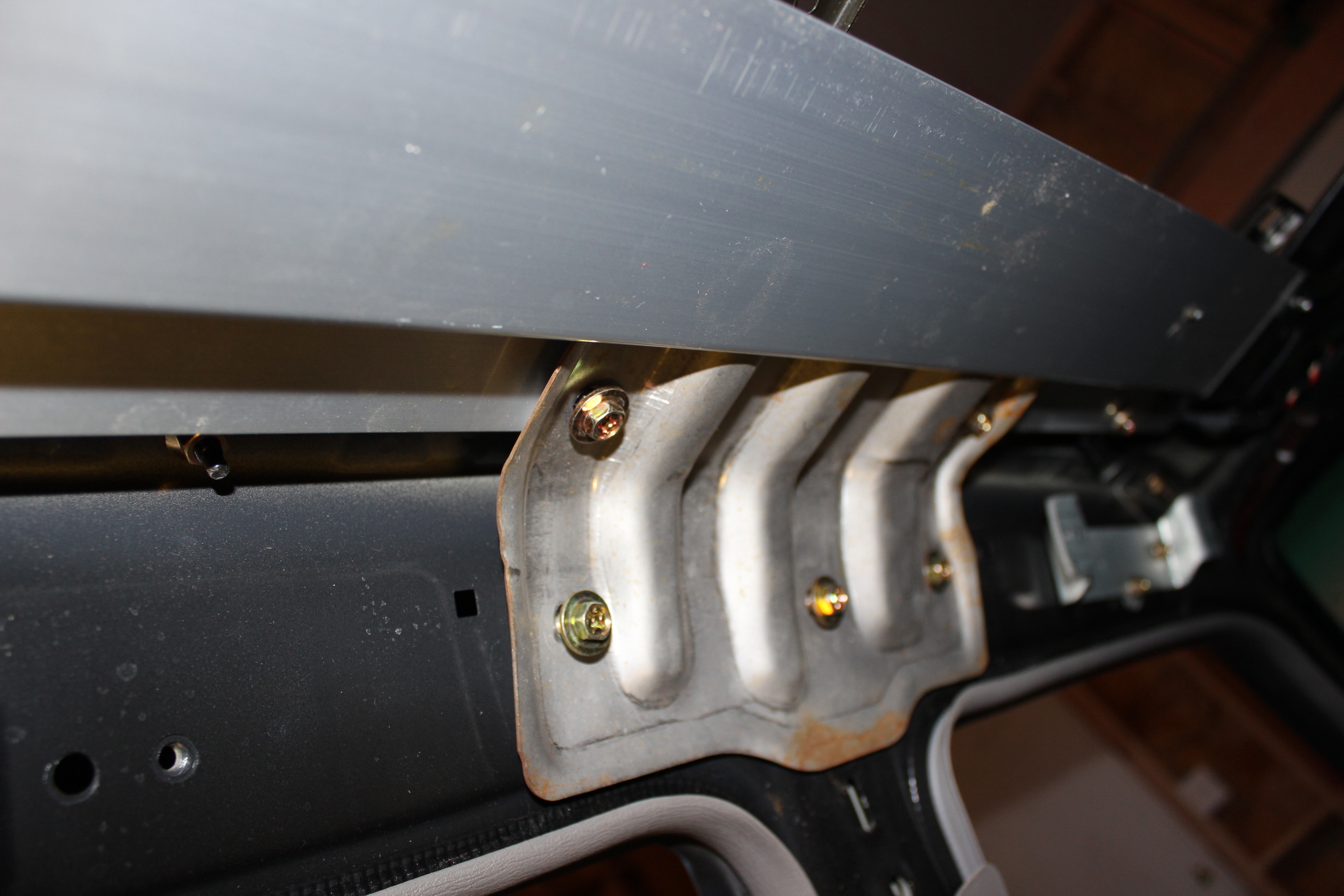
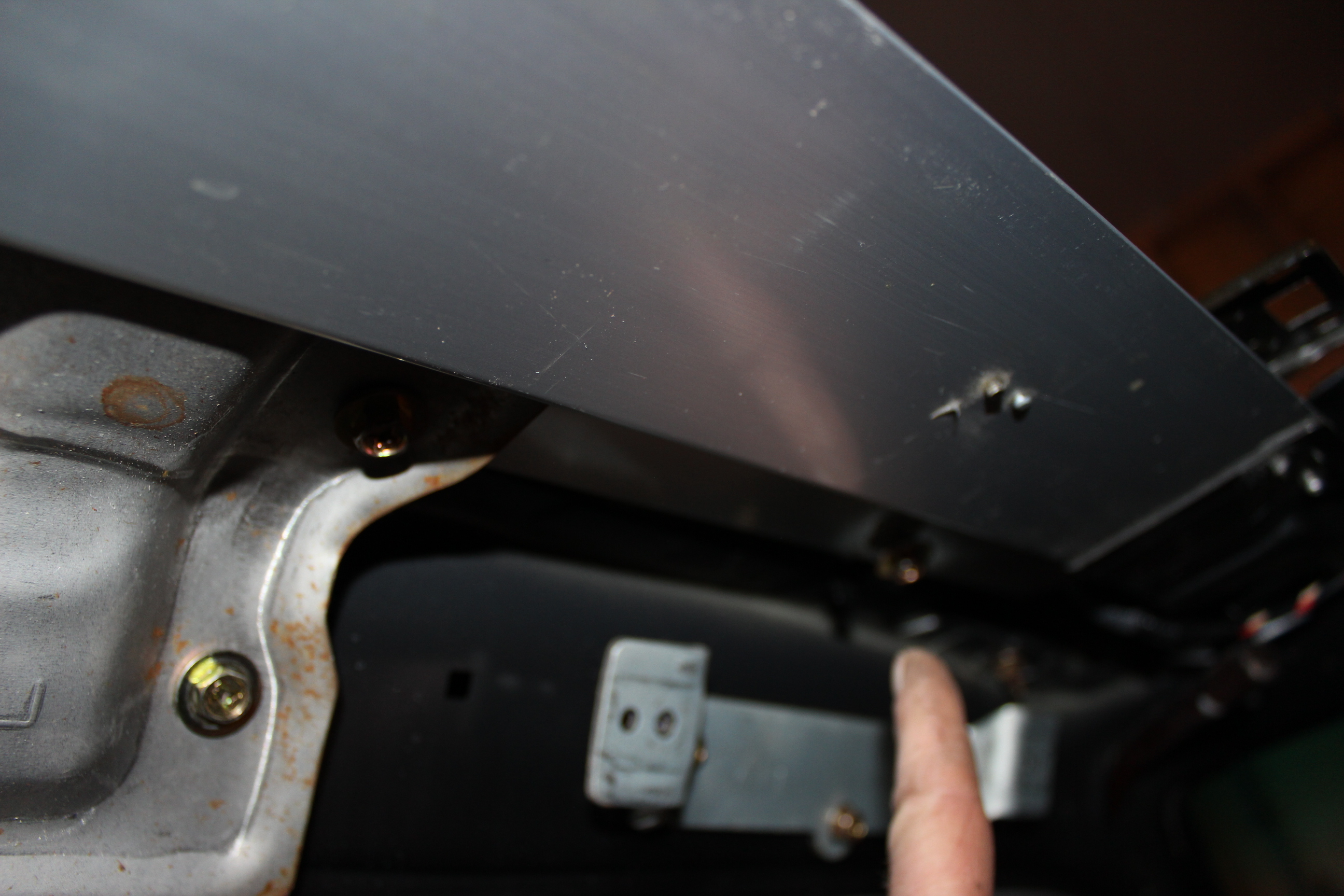
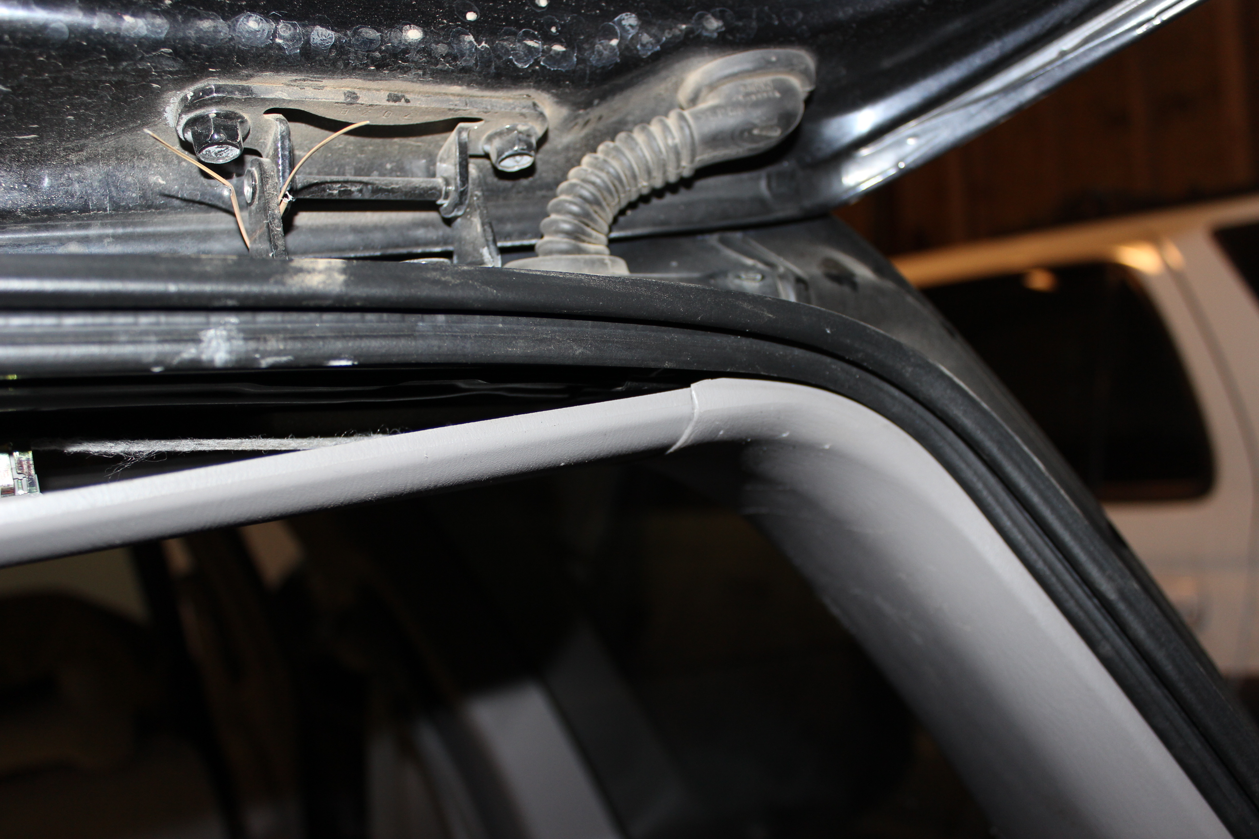
The next photos show the front bolts, rear bolts. Slip the assembly up on the front bolts and attach the nuts loosely. Then flex the bracket with the motor to slide the slotted holes onto the rear bolts w/o having to remove the nuts. Press the assembly up with your shoulder and tighten the rear nuts. The following shots show bolts to install. These shots are along the passenger side and progress rear to front, the same on the drivers as well. When all are in place tighten from rear to front including the two front nuts.
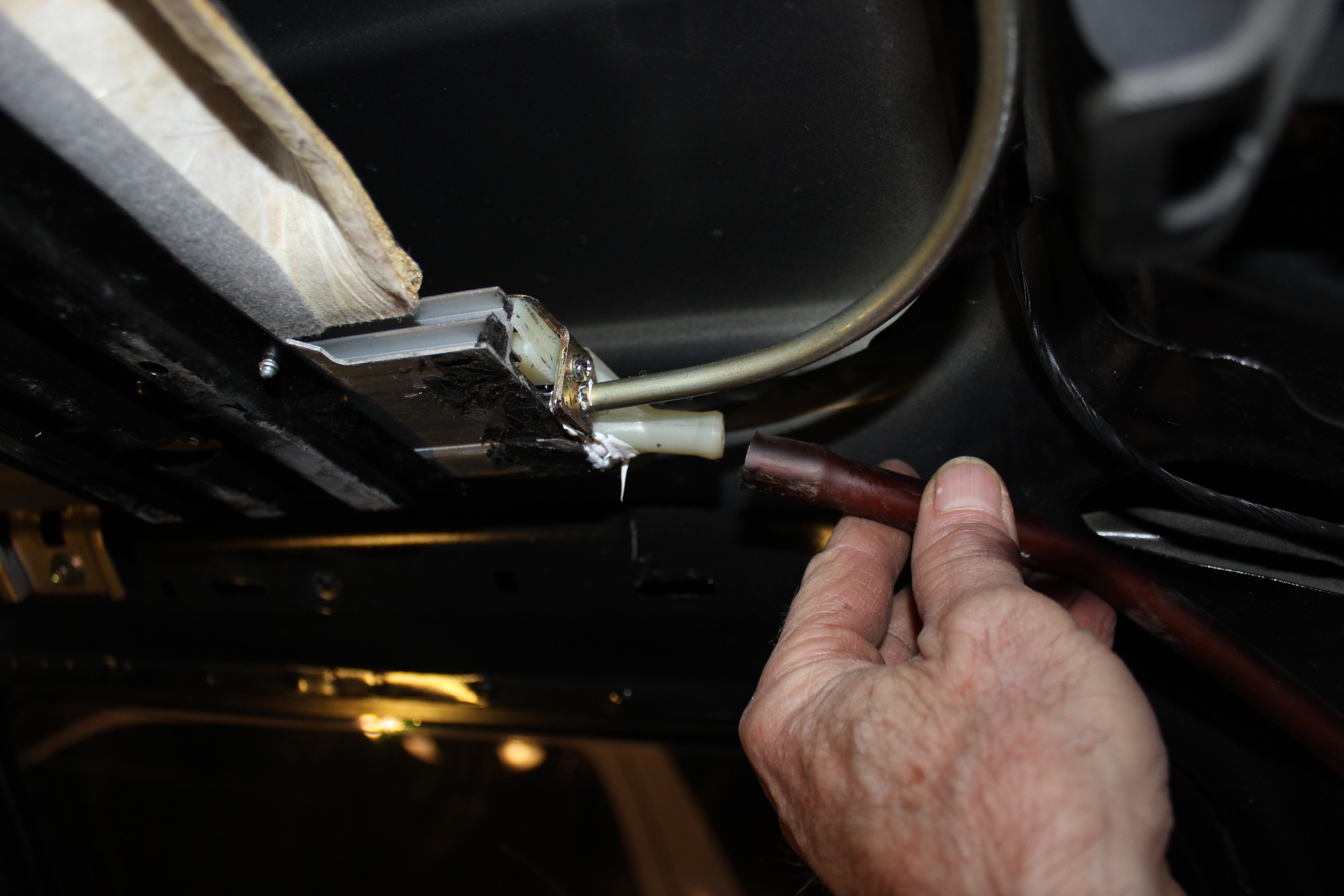
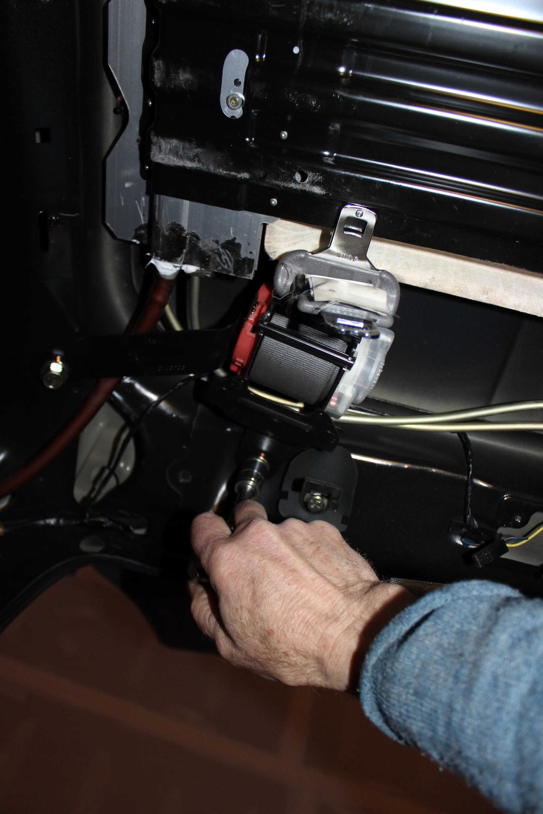
The center light wire gets snapped into the cross member, all four drain hoses slipped in place. You may want to blow out the hoses to make sure they drain well. Then the rear seat belt assembly in the back right corner. I then placed the glass on the sliders and shimmed it to height and tightened the bolts. This could wait to be the last step if you prefer that.
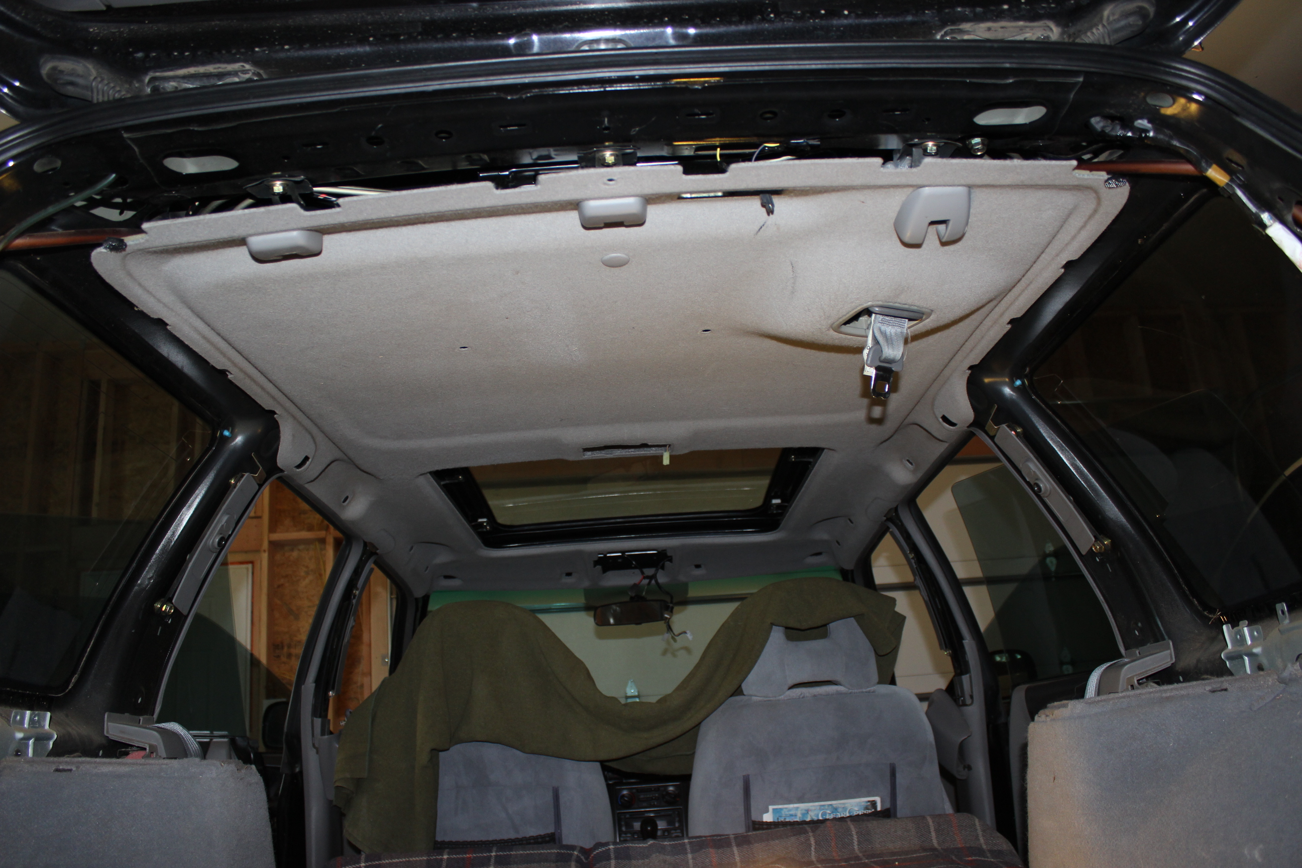
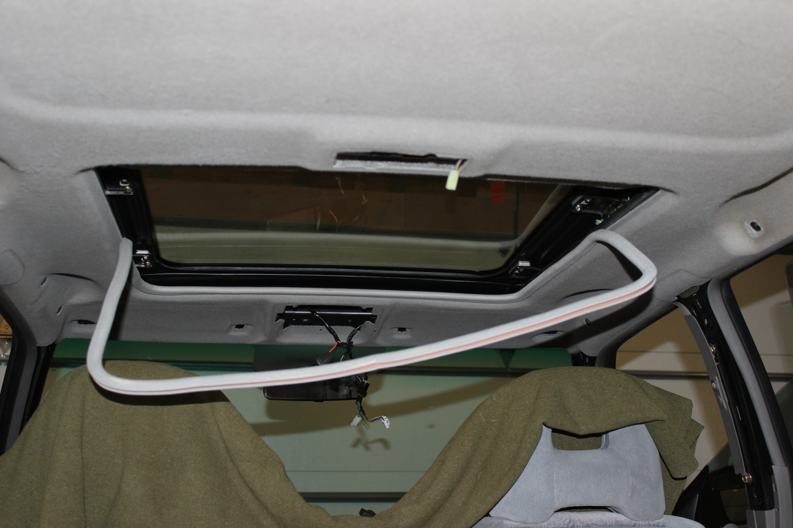
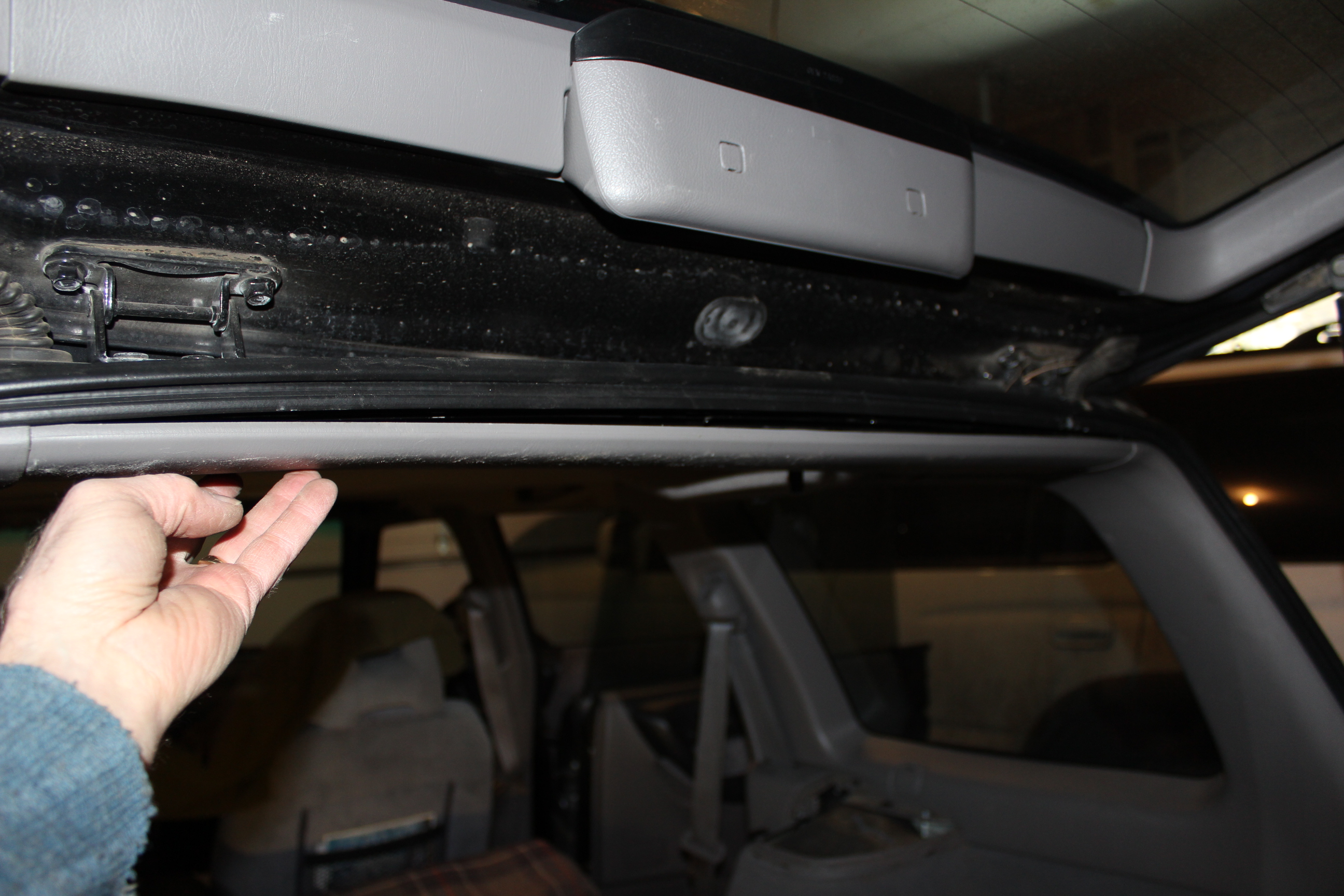
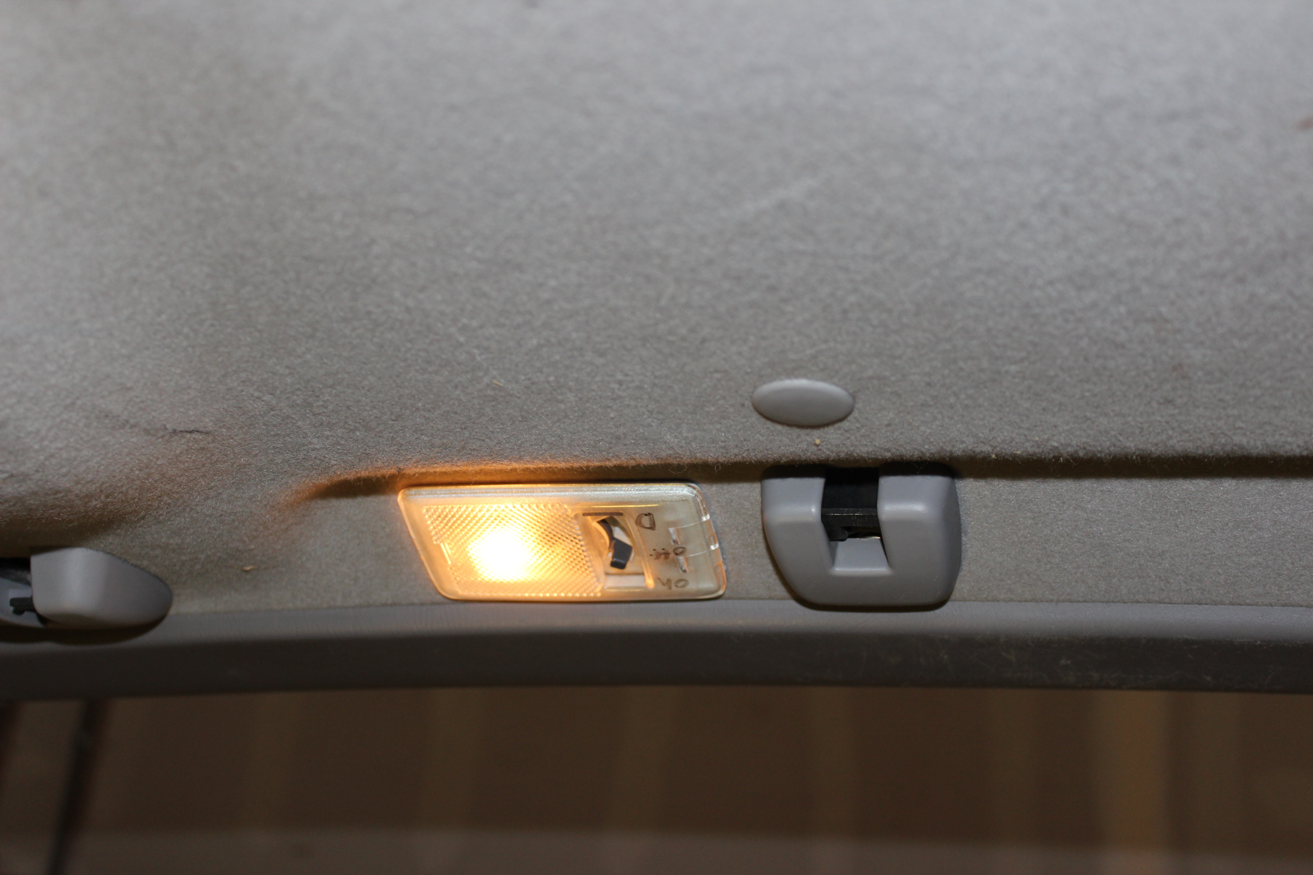
Headliner goes in like the rack did. Set in place then slip the edges in place on one side. While holding it in place, slip it up and into the other side. It kind of flexes a bit and then snaps in place loosely. Locate it forward/back using the hand hold bolt holes as alignment queues. Slip on the sunroof trim strip and attach the center light. Test it!
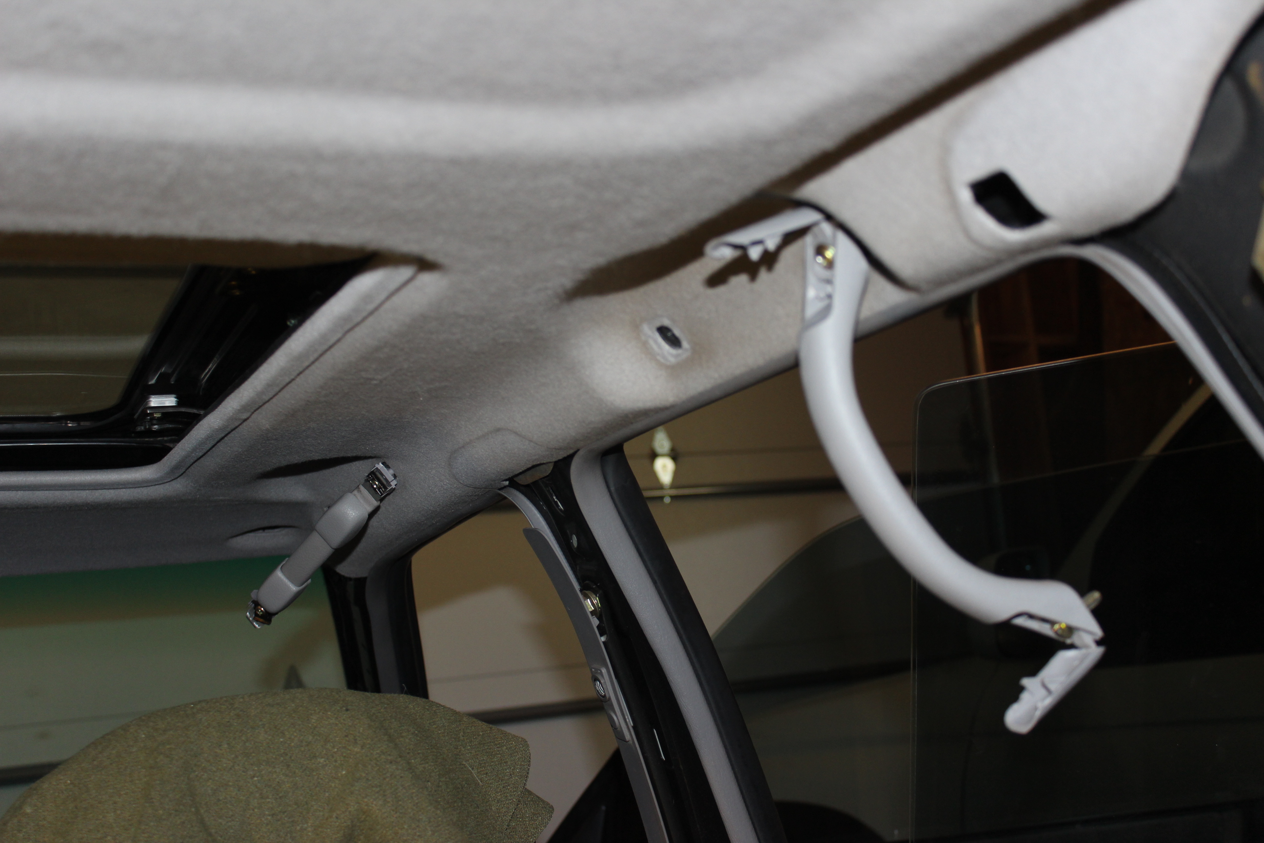
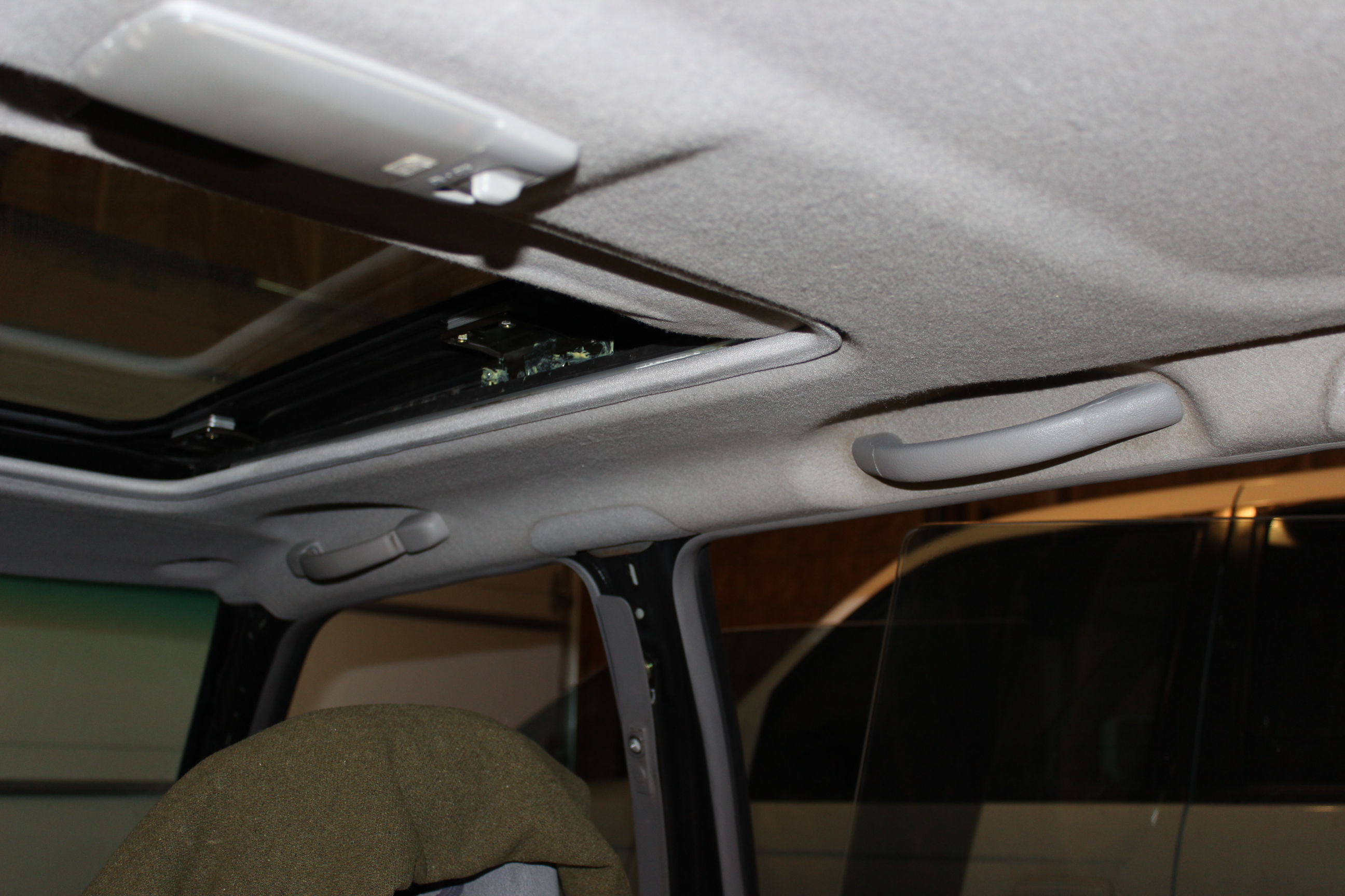
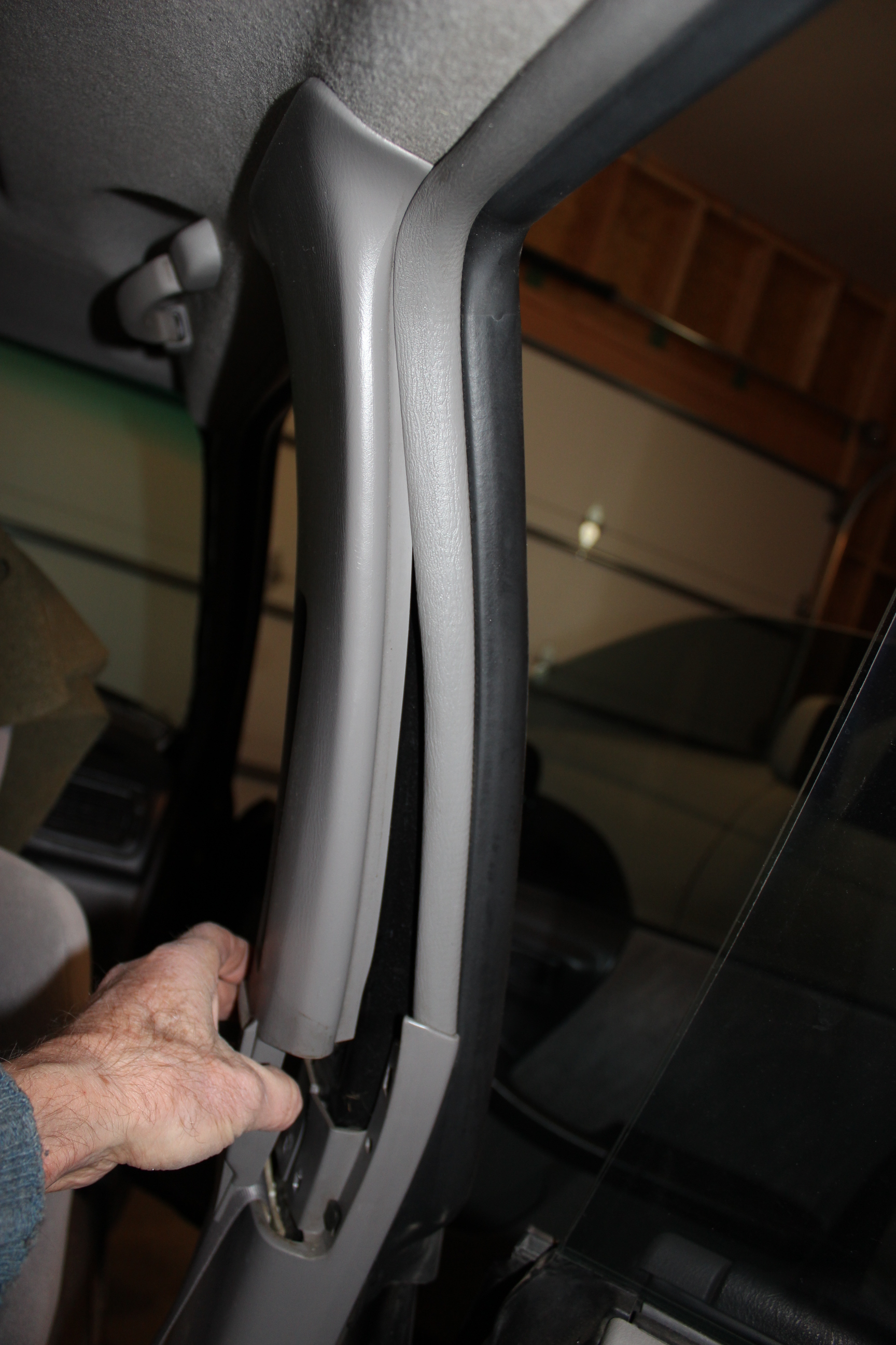
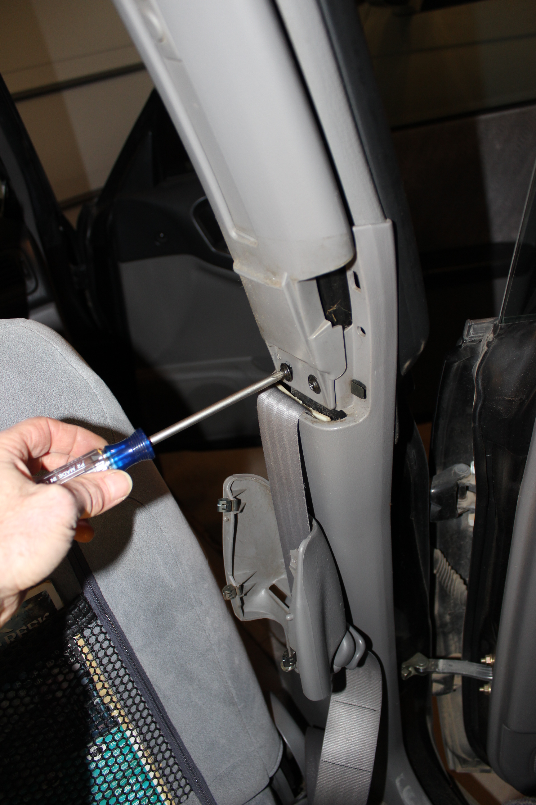
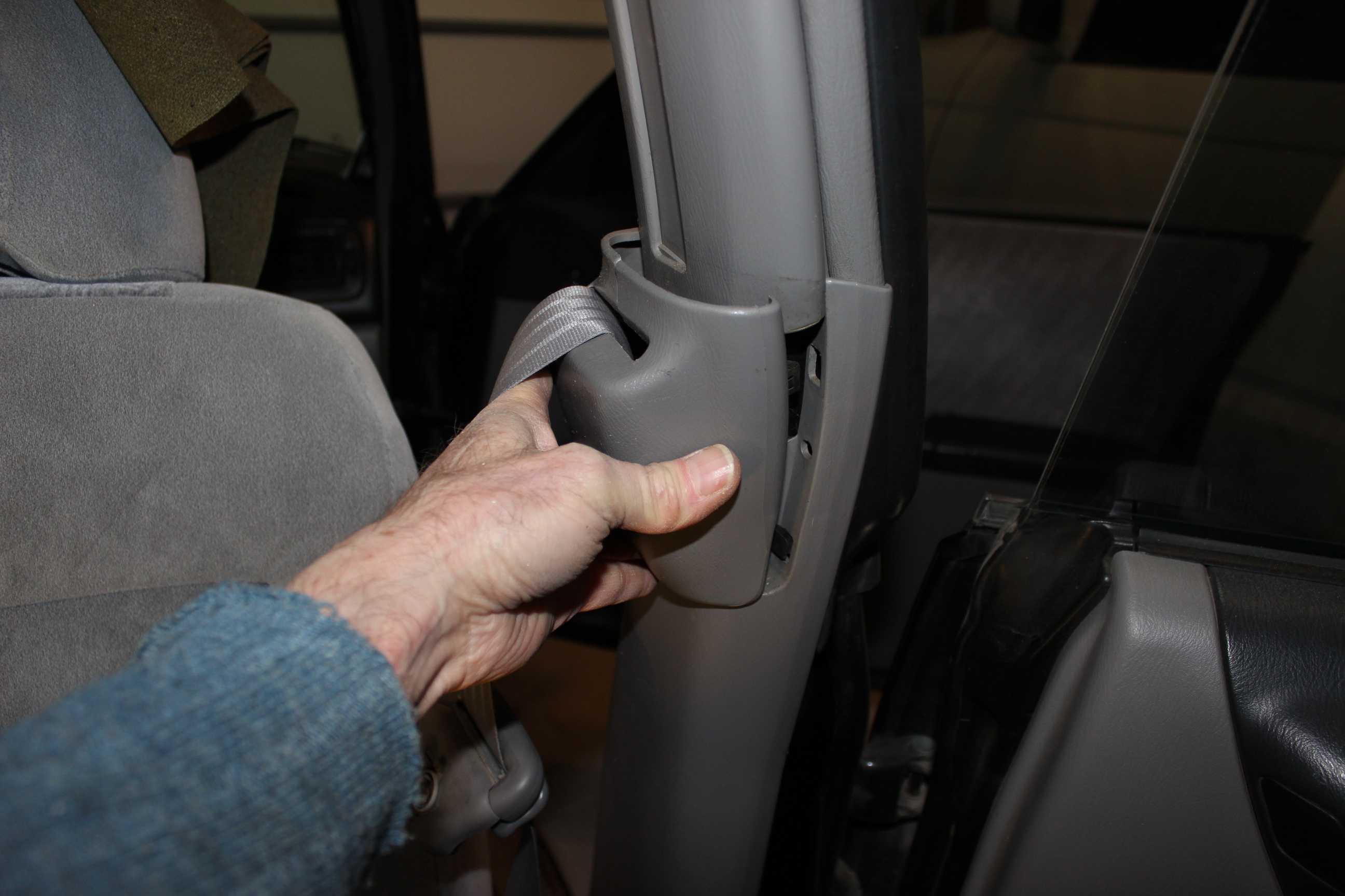
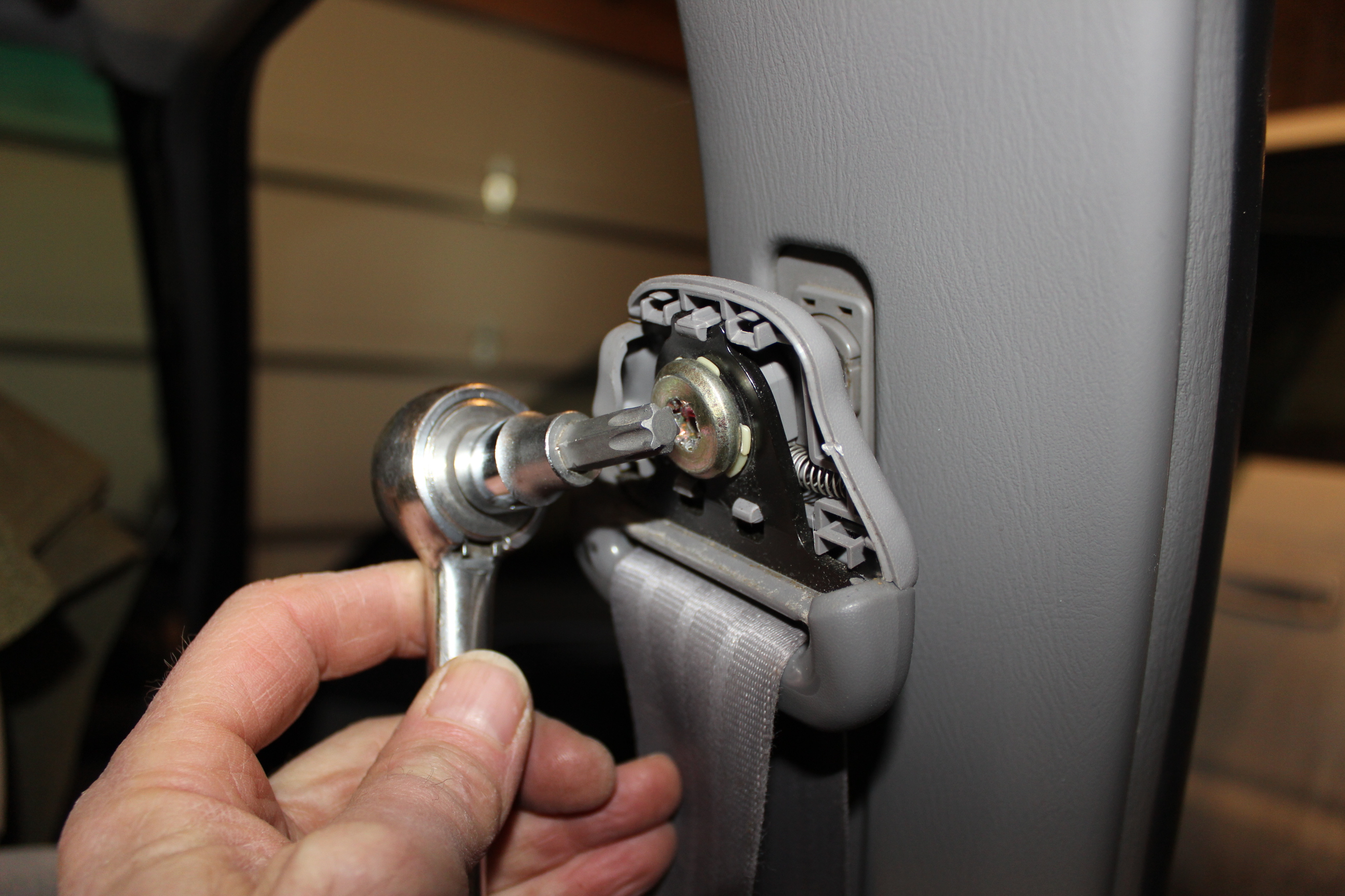
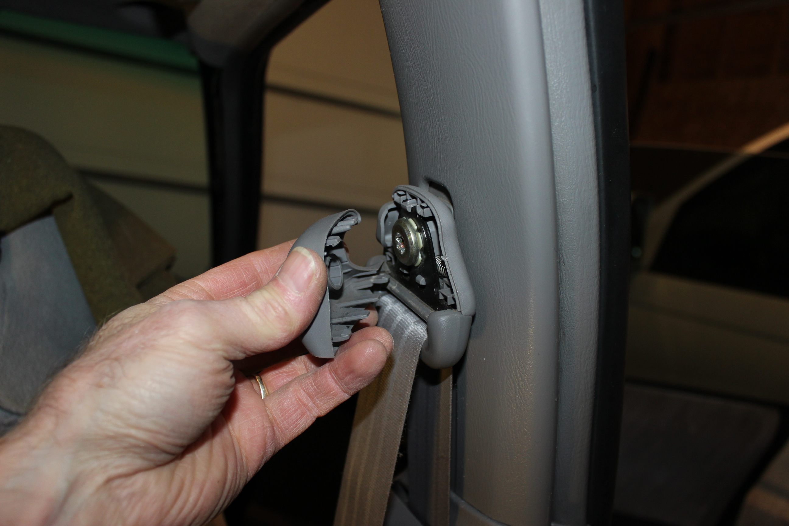
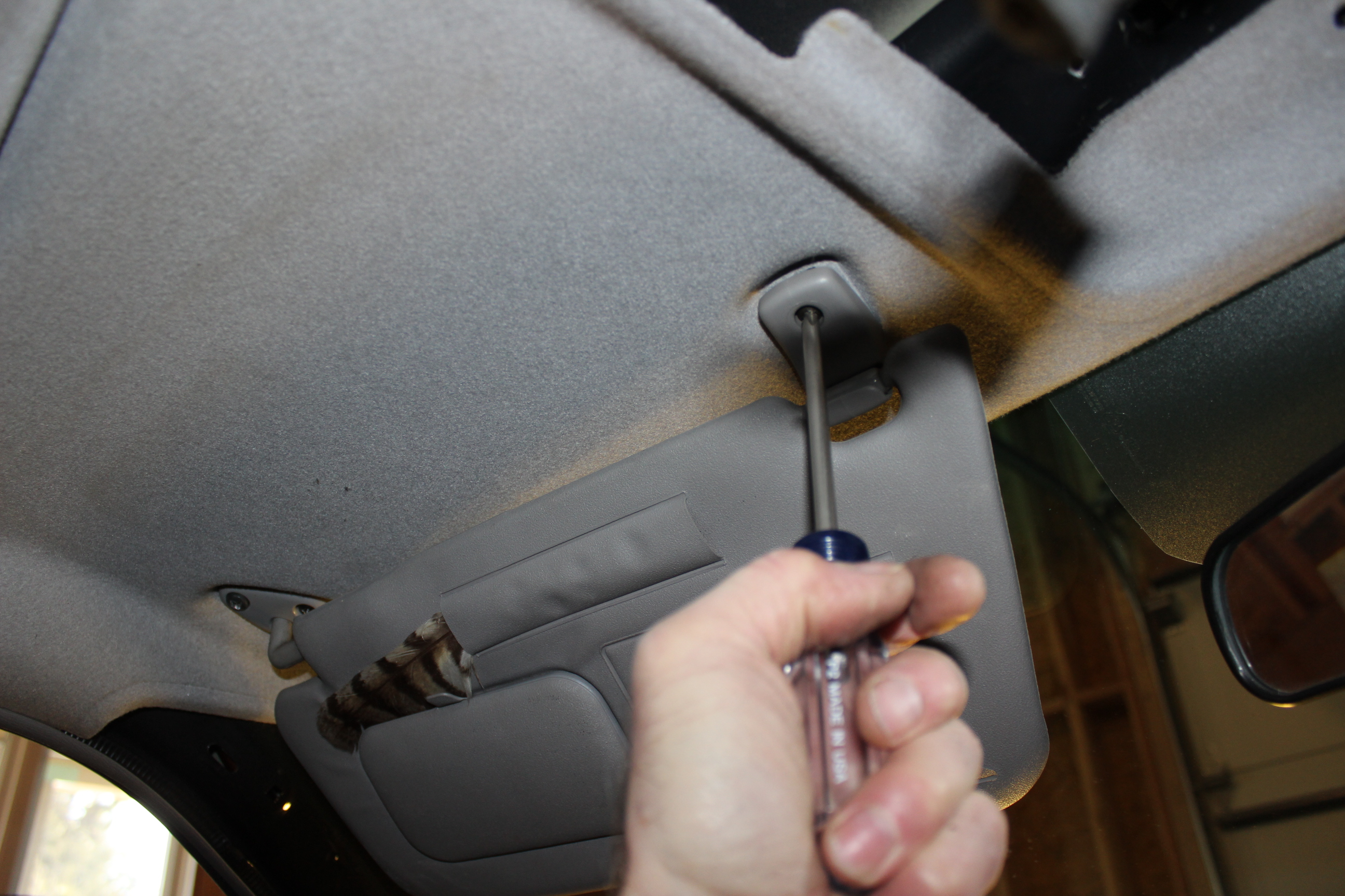
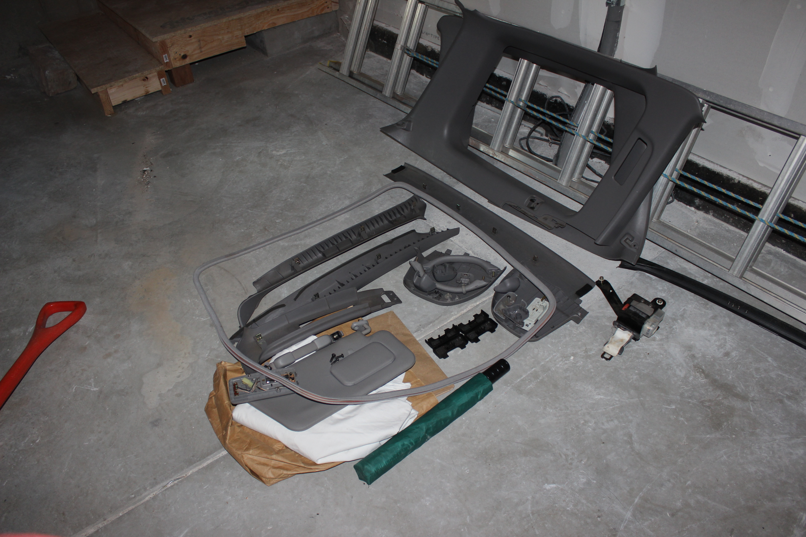
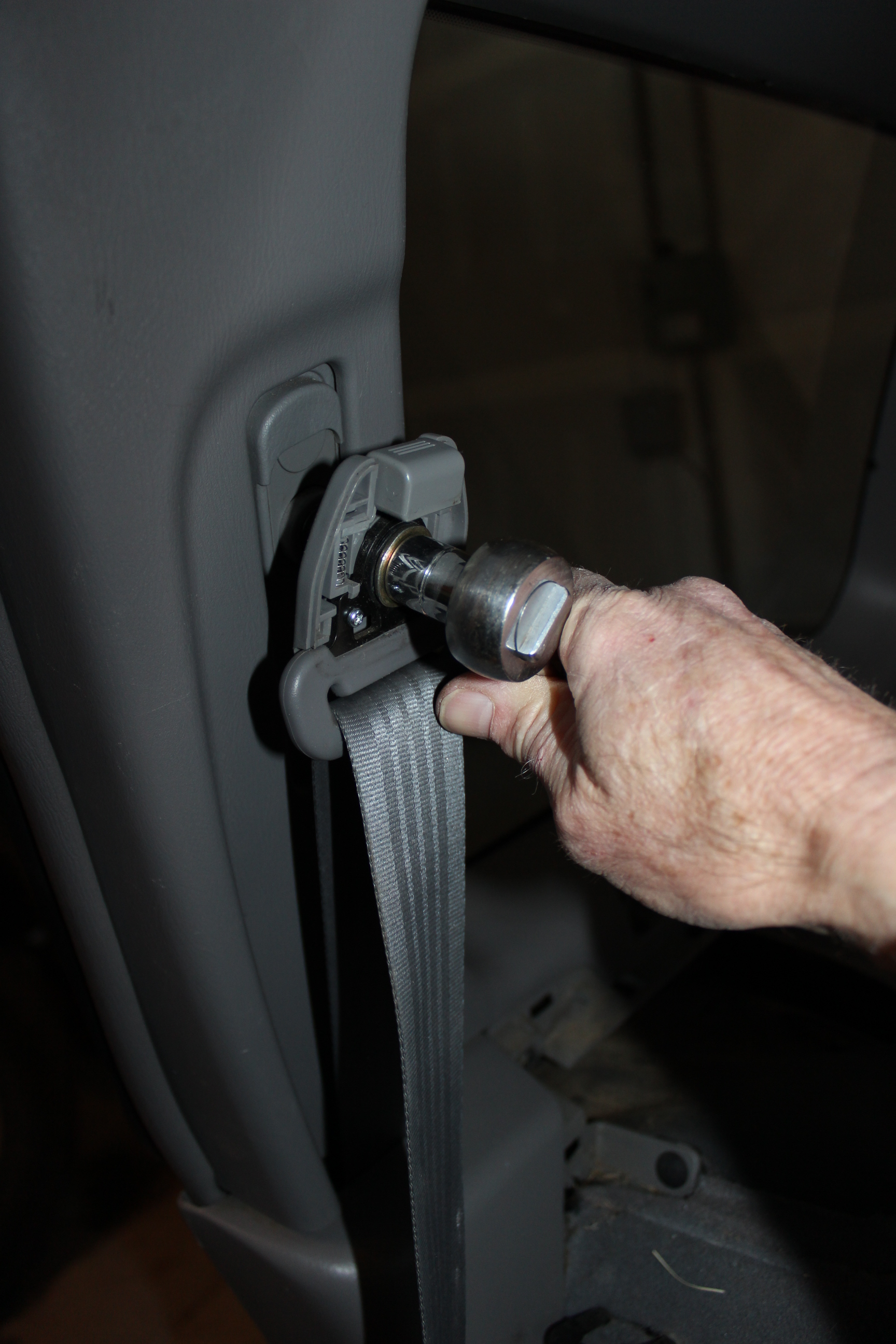
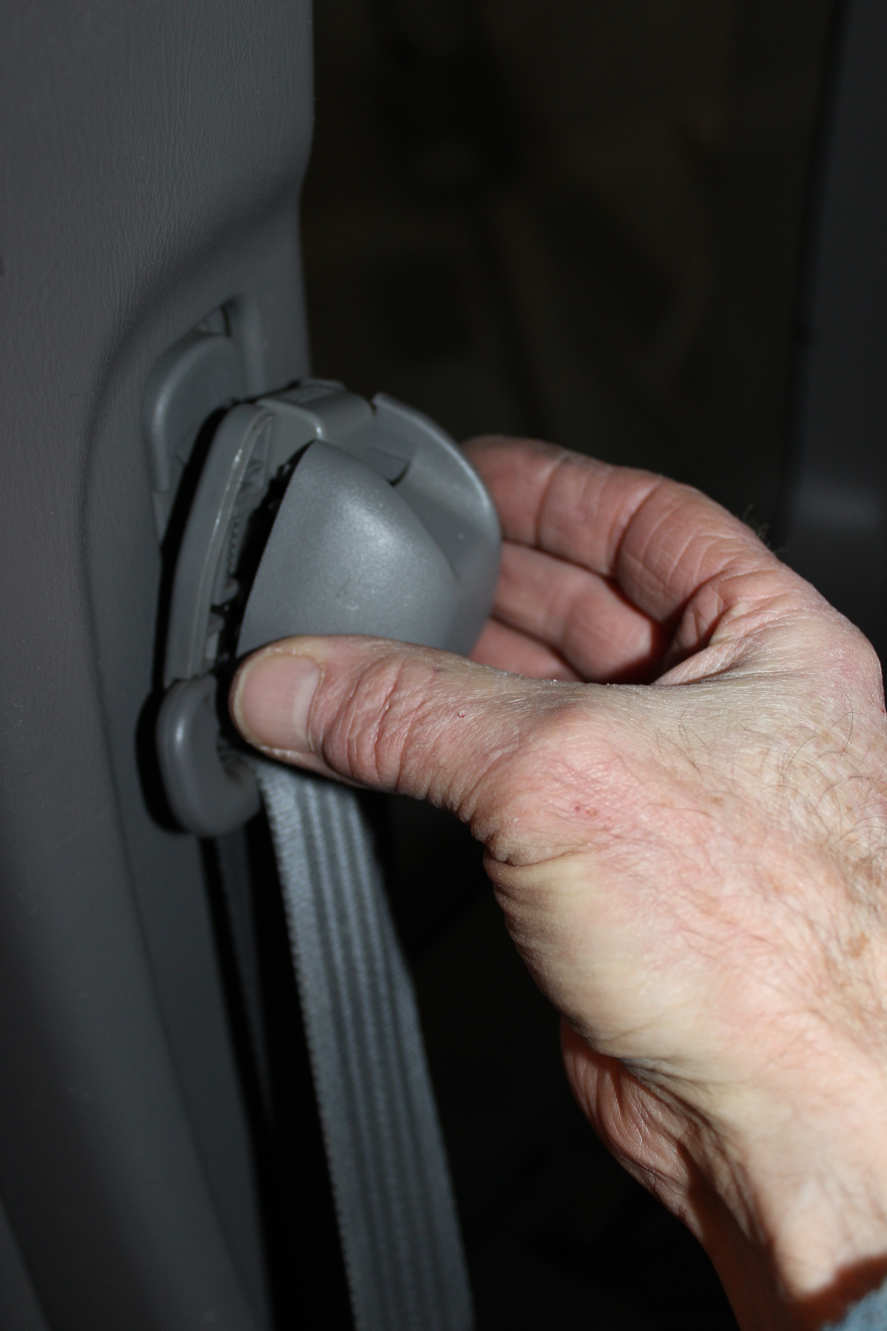
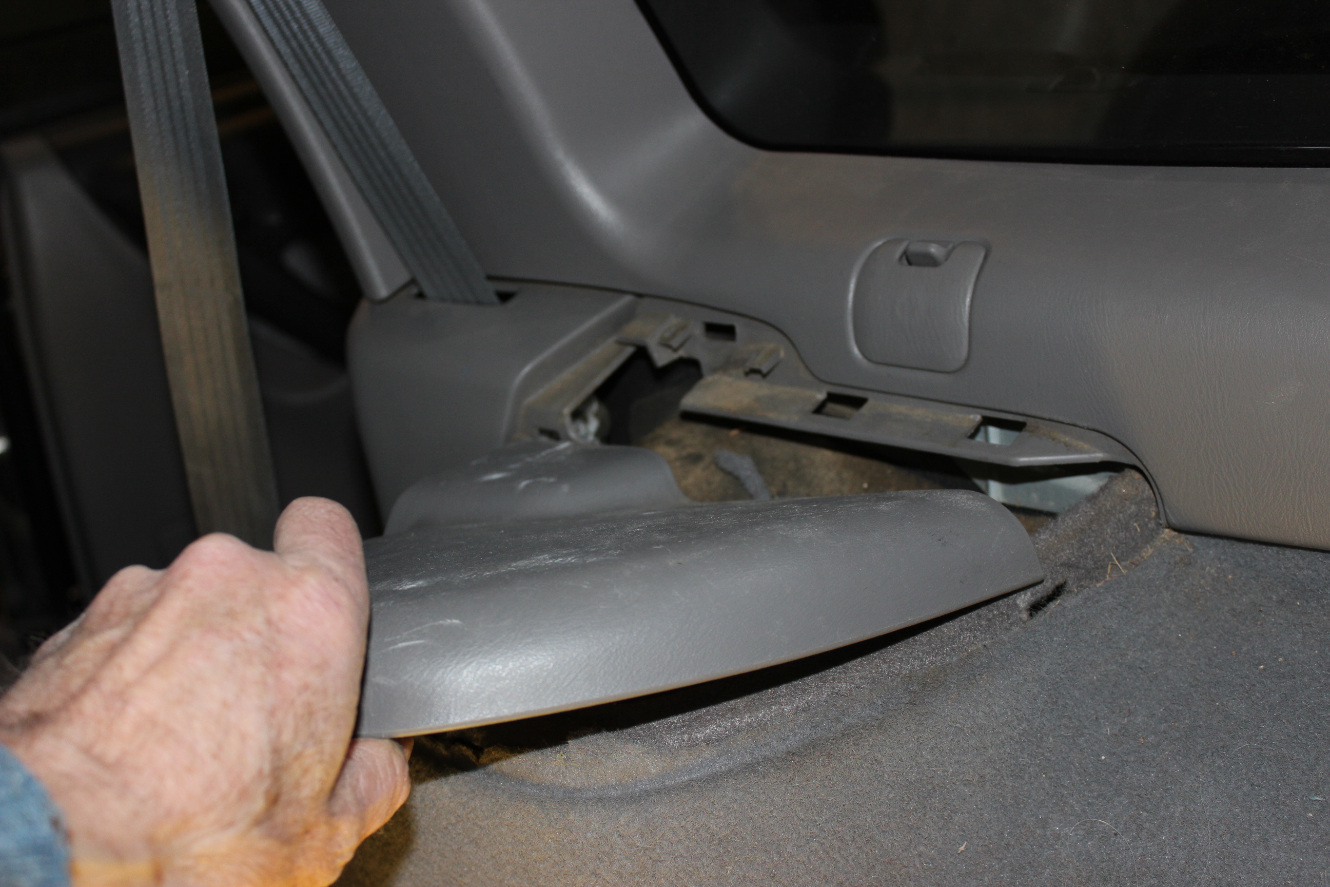
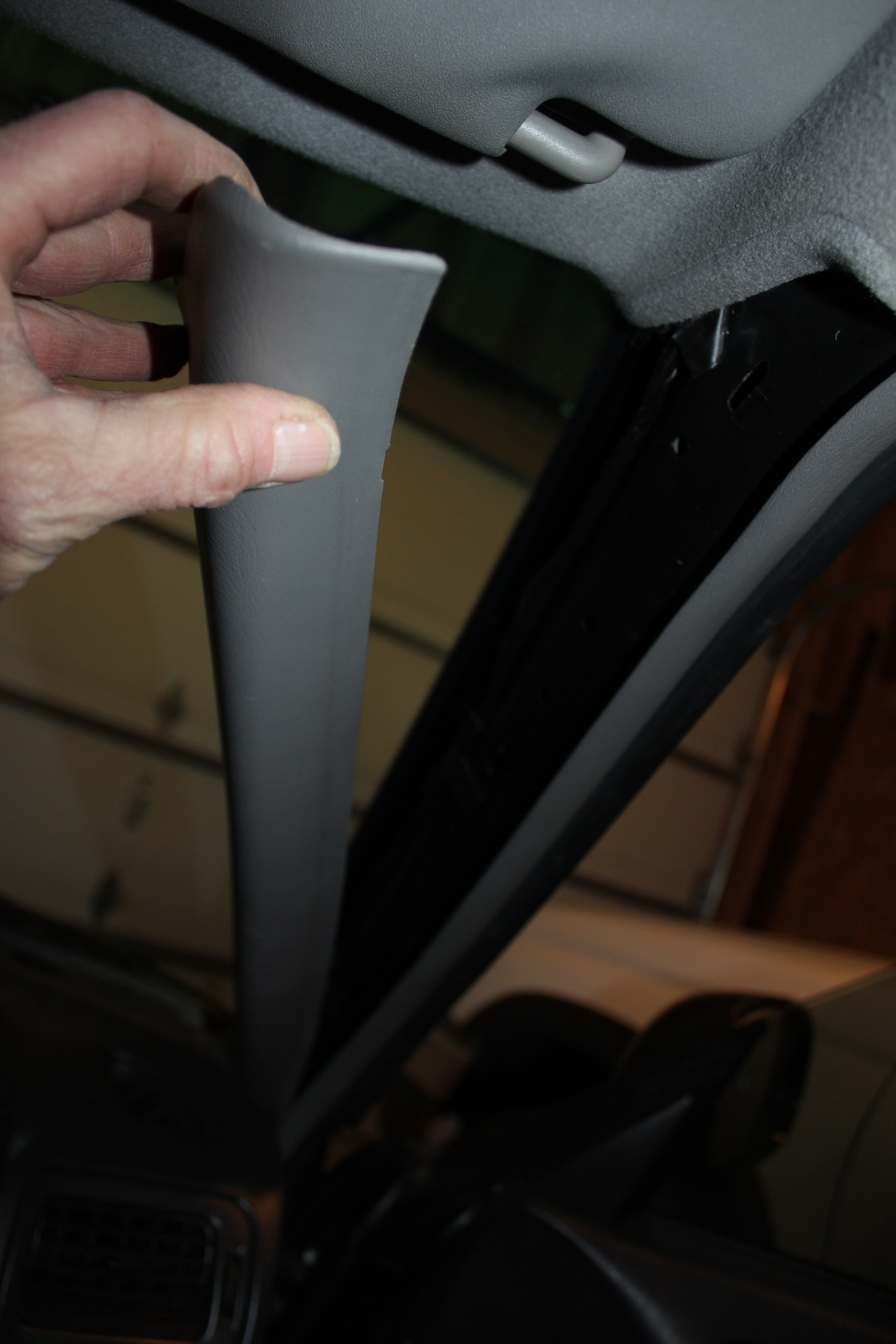
Grab handles, the sliding luggage type one goes on the font. Side column trim snap and screw in place. Use your Torx adapter to tighten the seatbelt and finish up with the cover pieces. My drivers side didn't have a grab bar, just some plugs. Visors on.
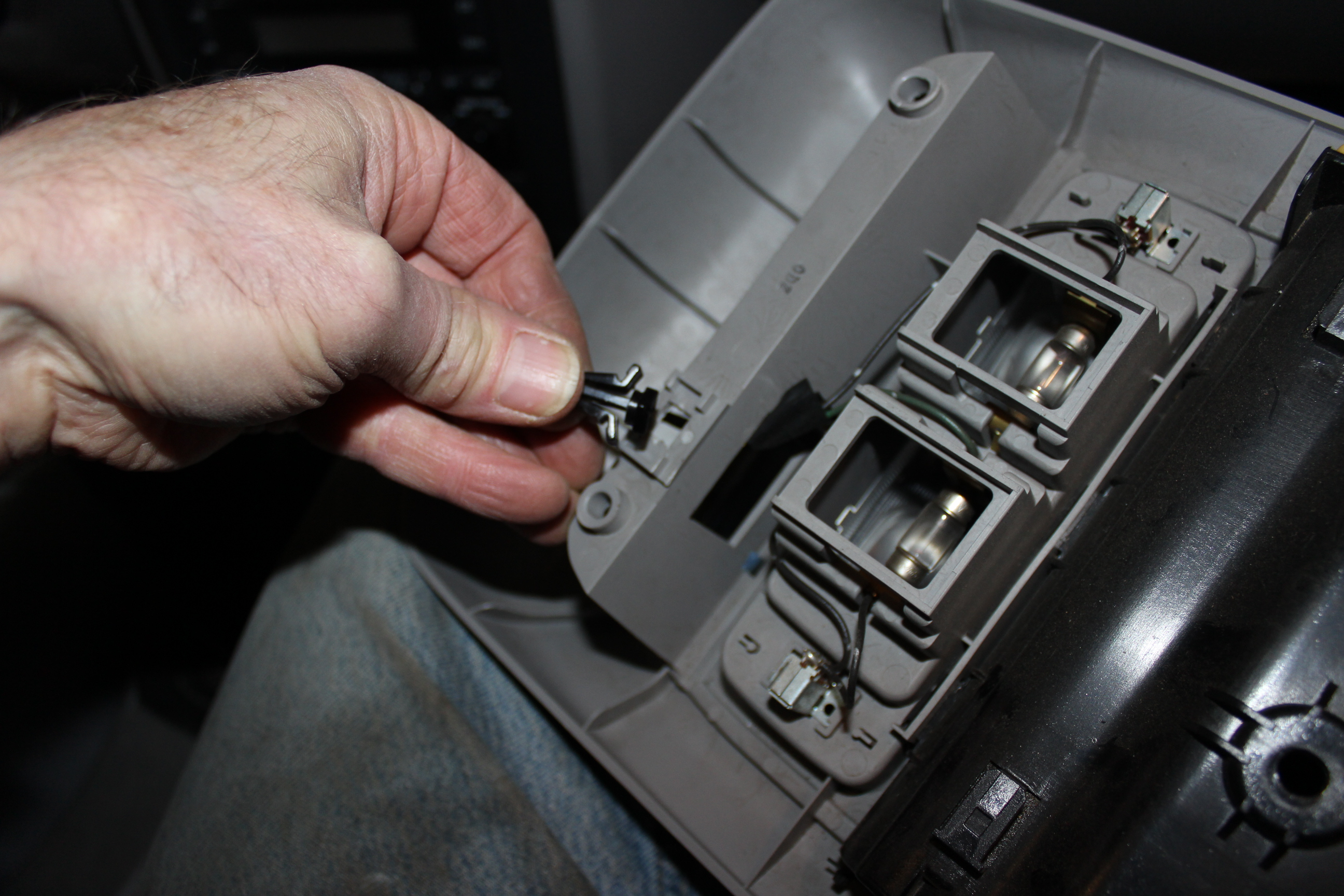
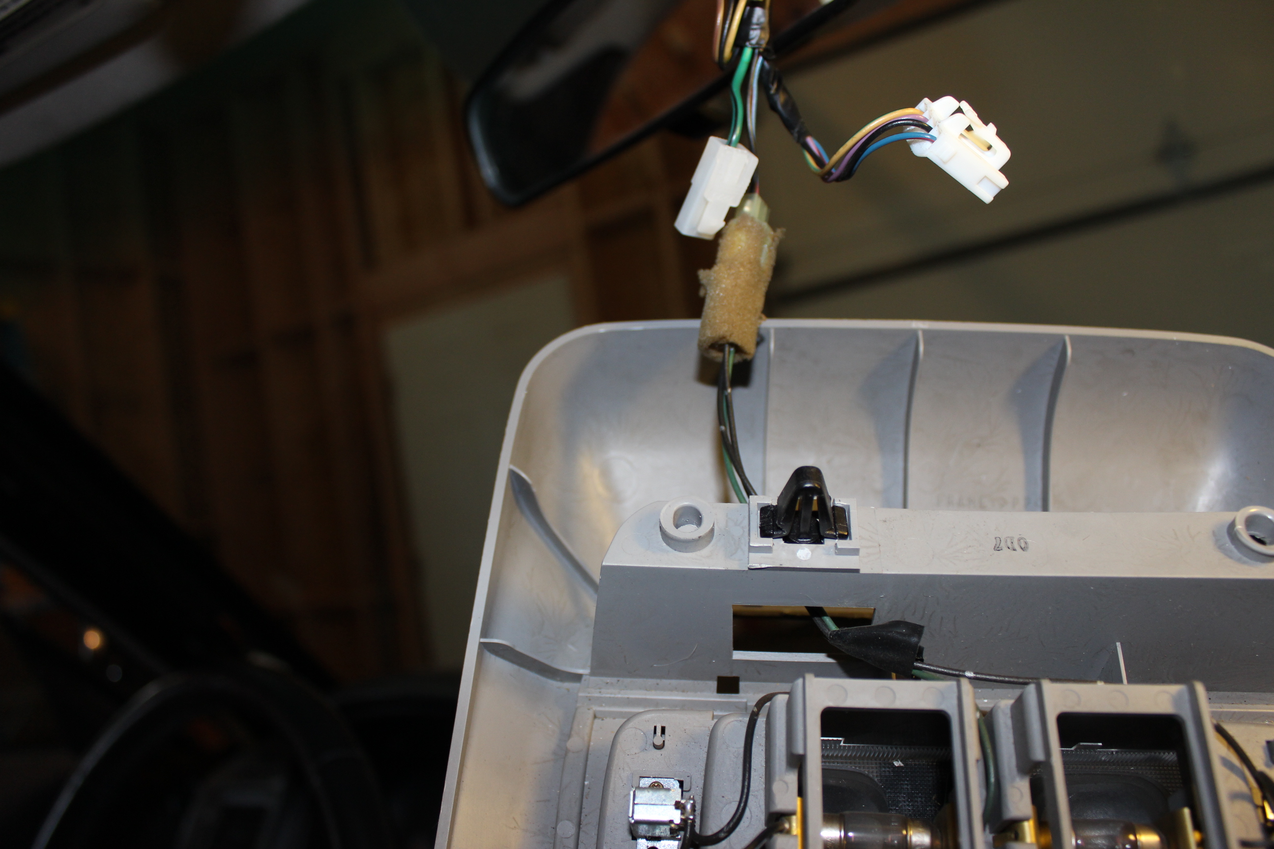
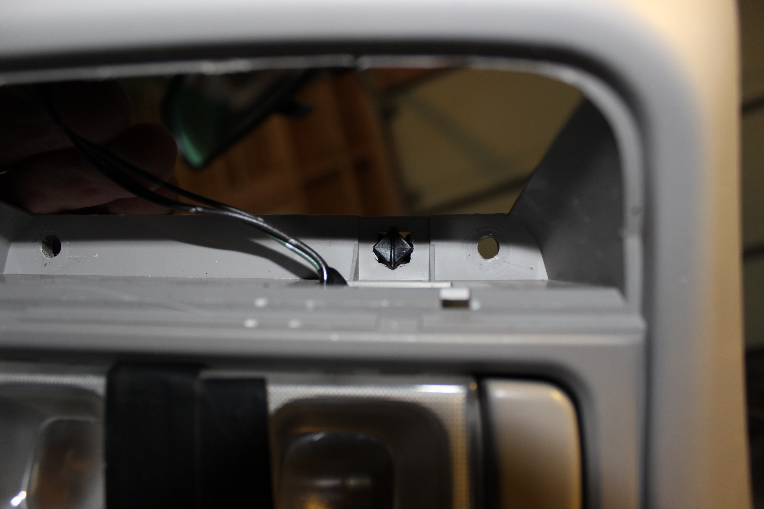
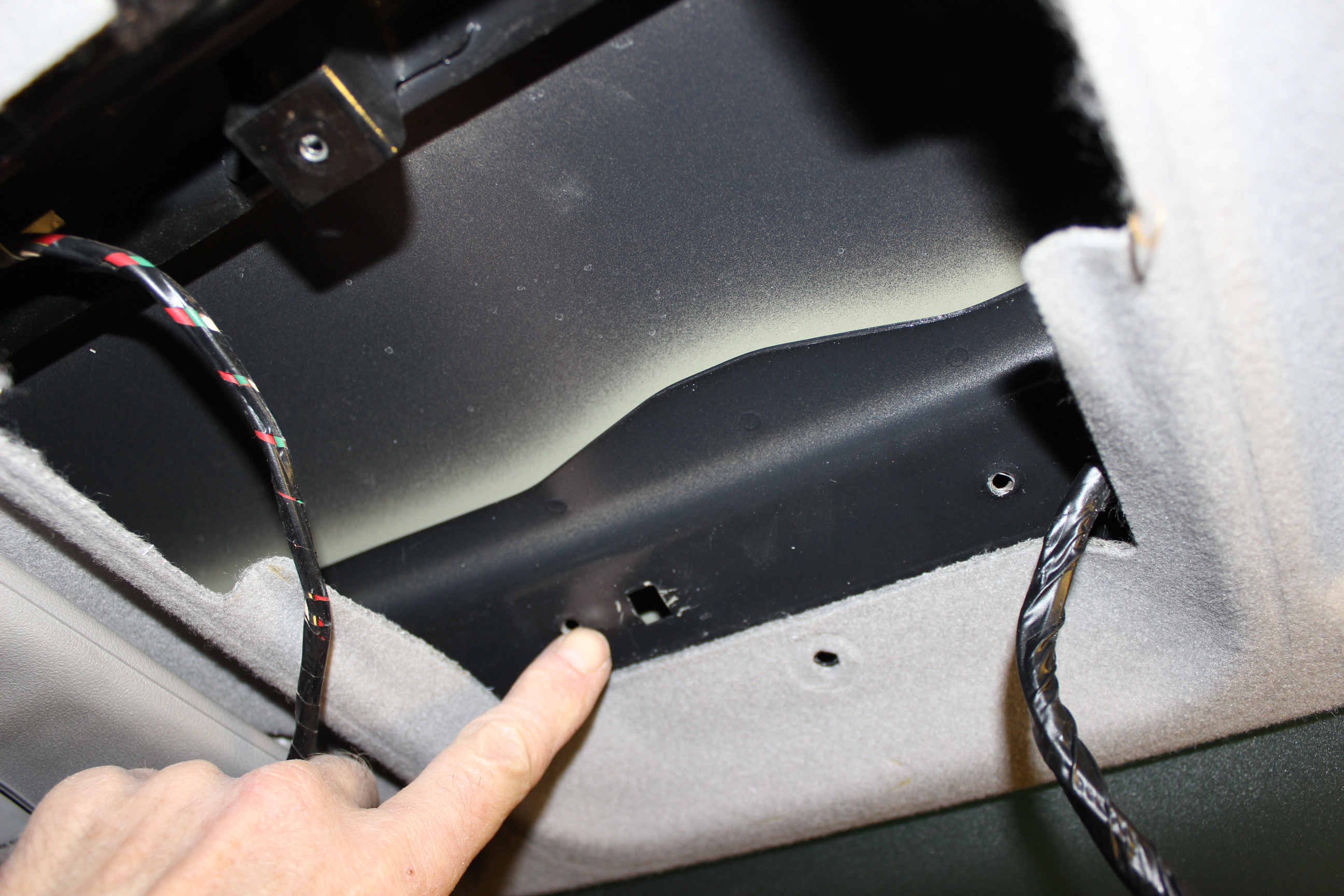
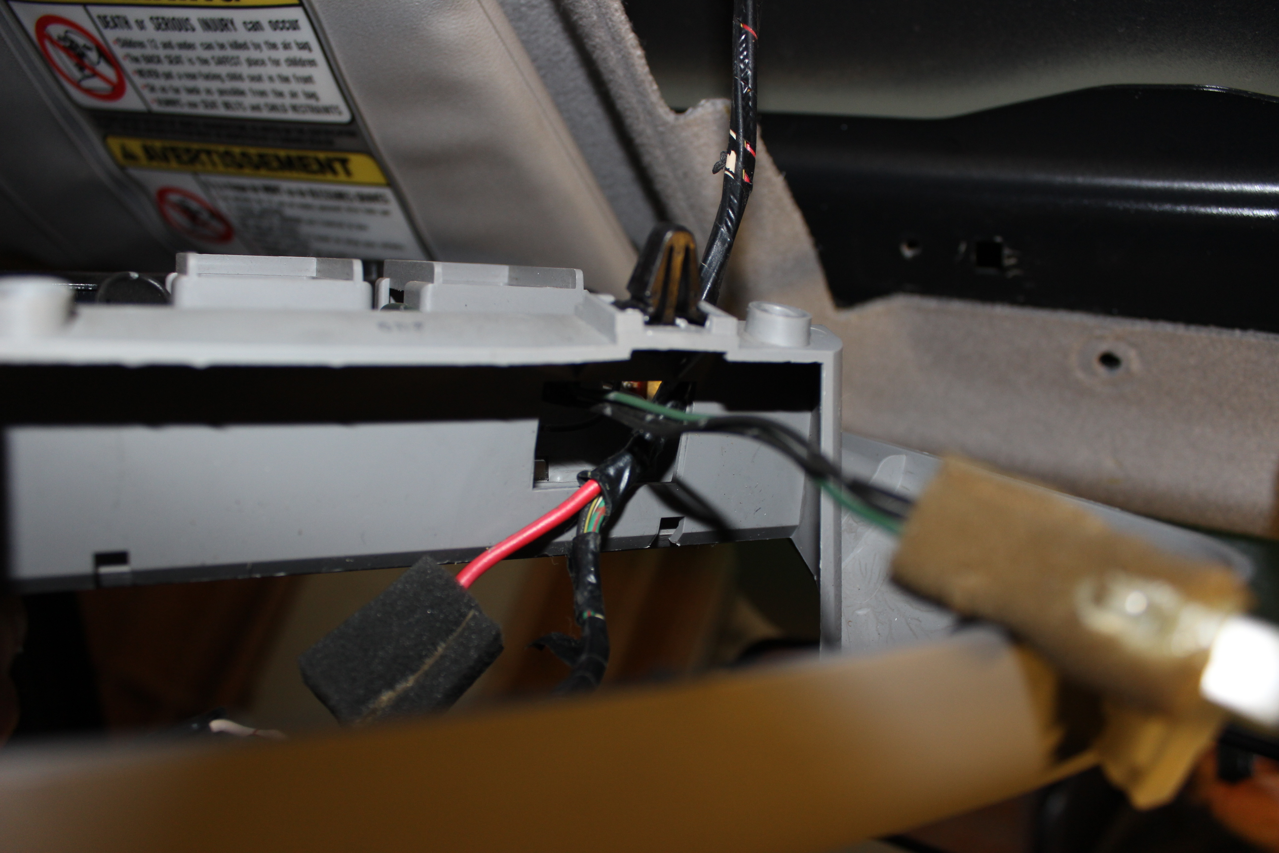
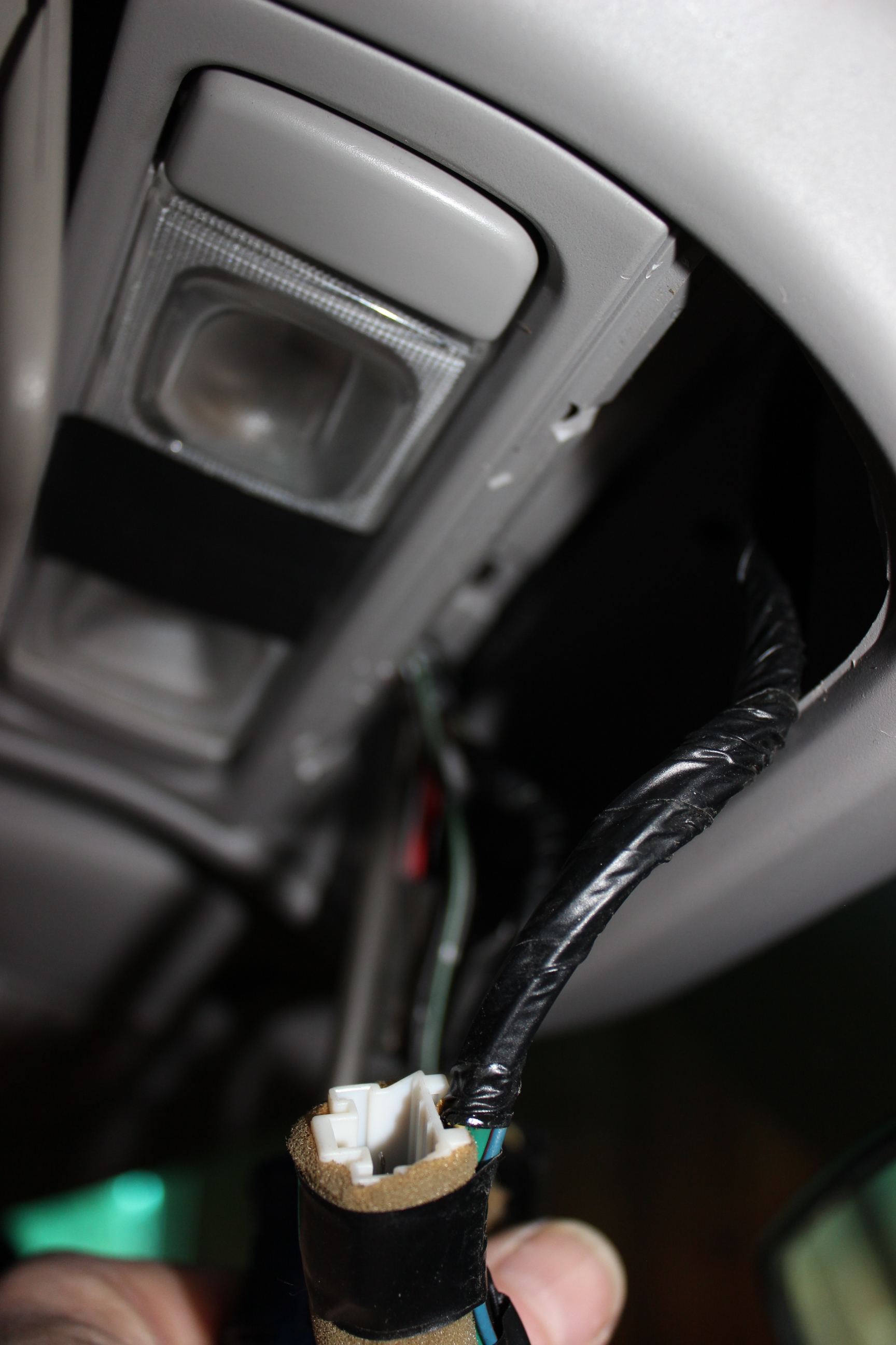
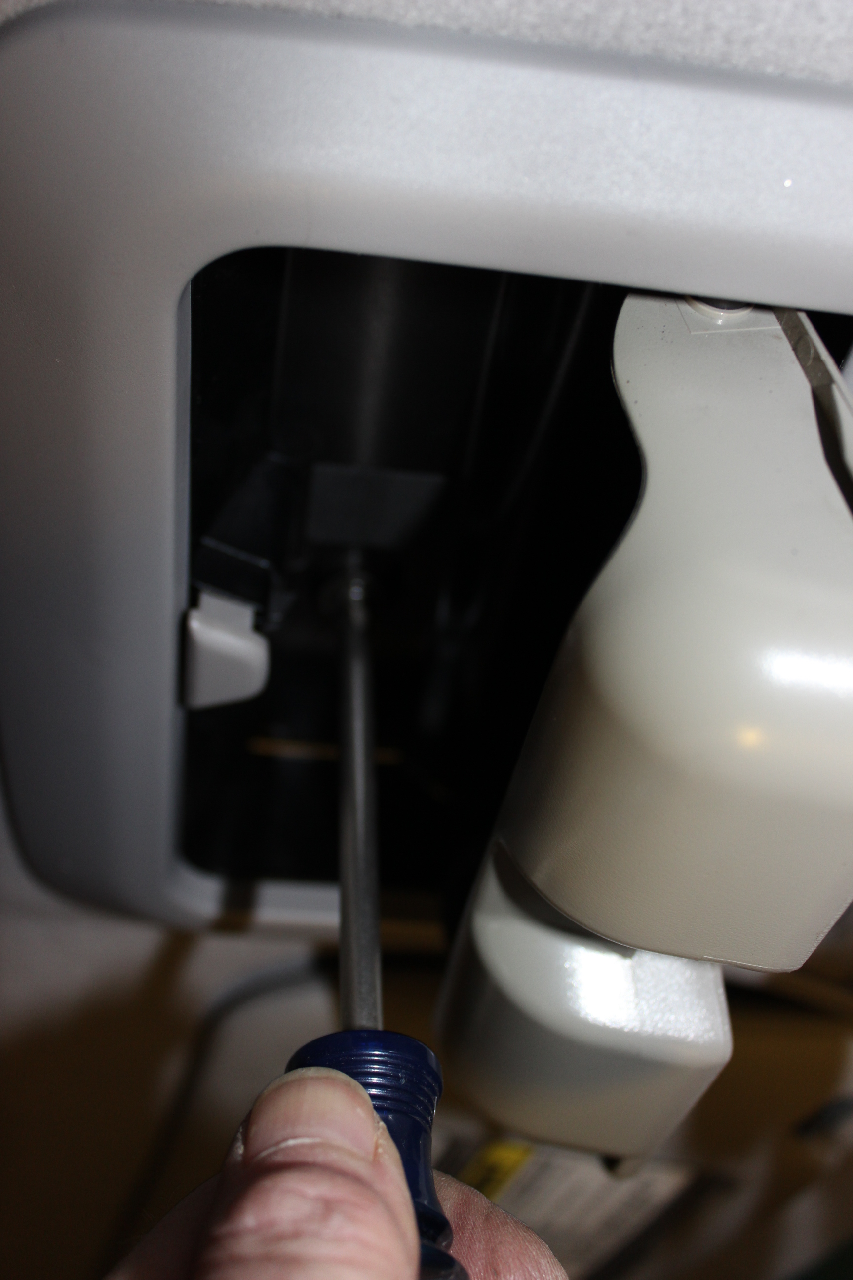
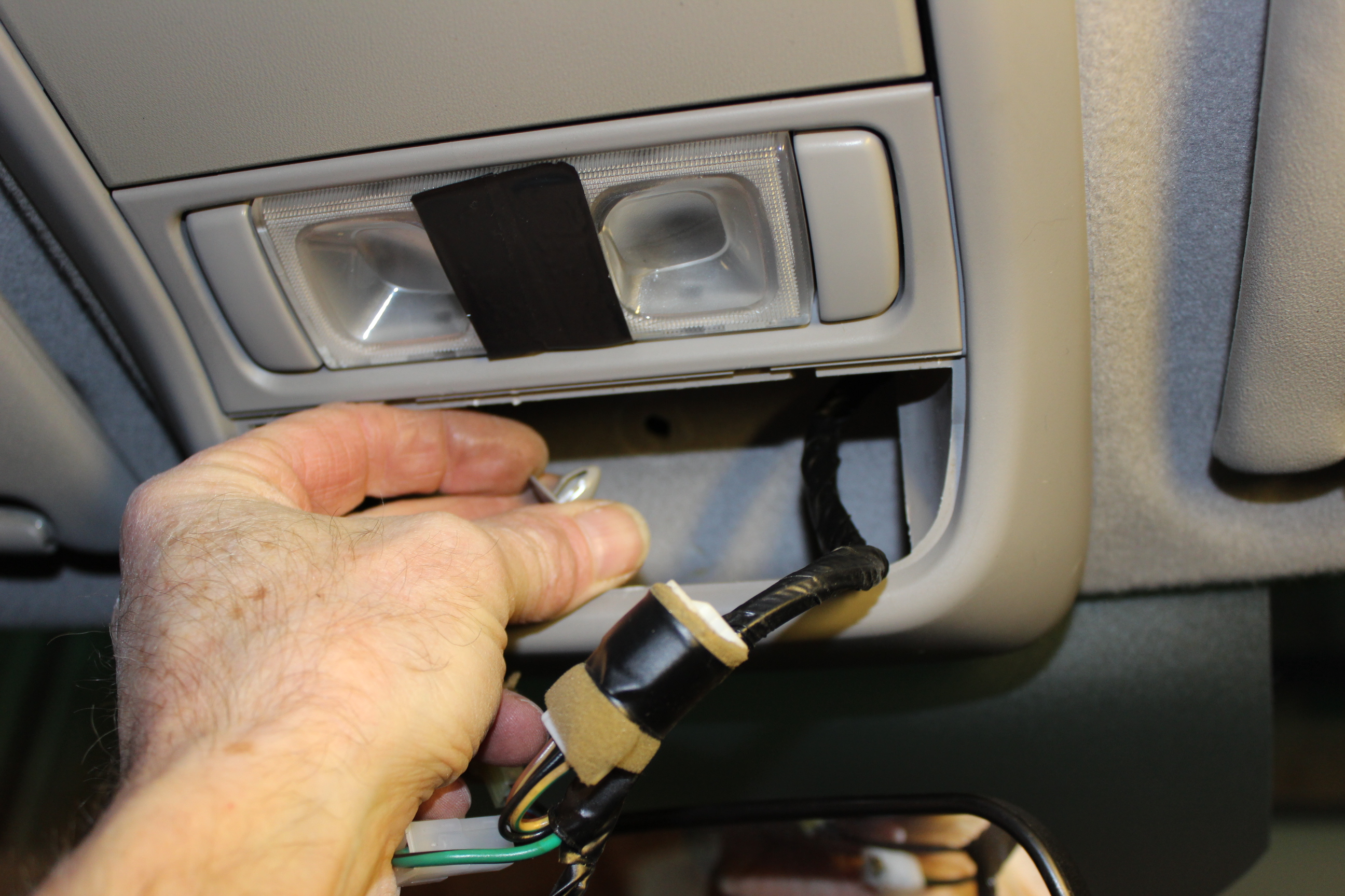
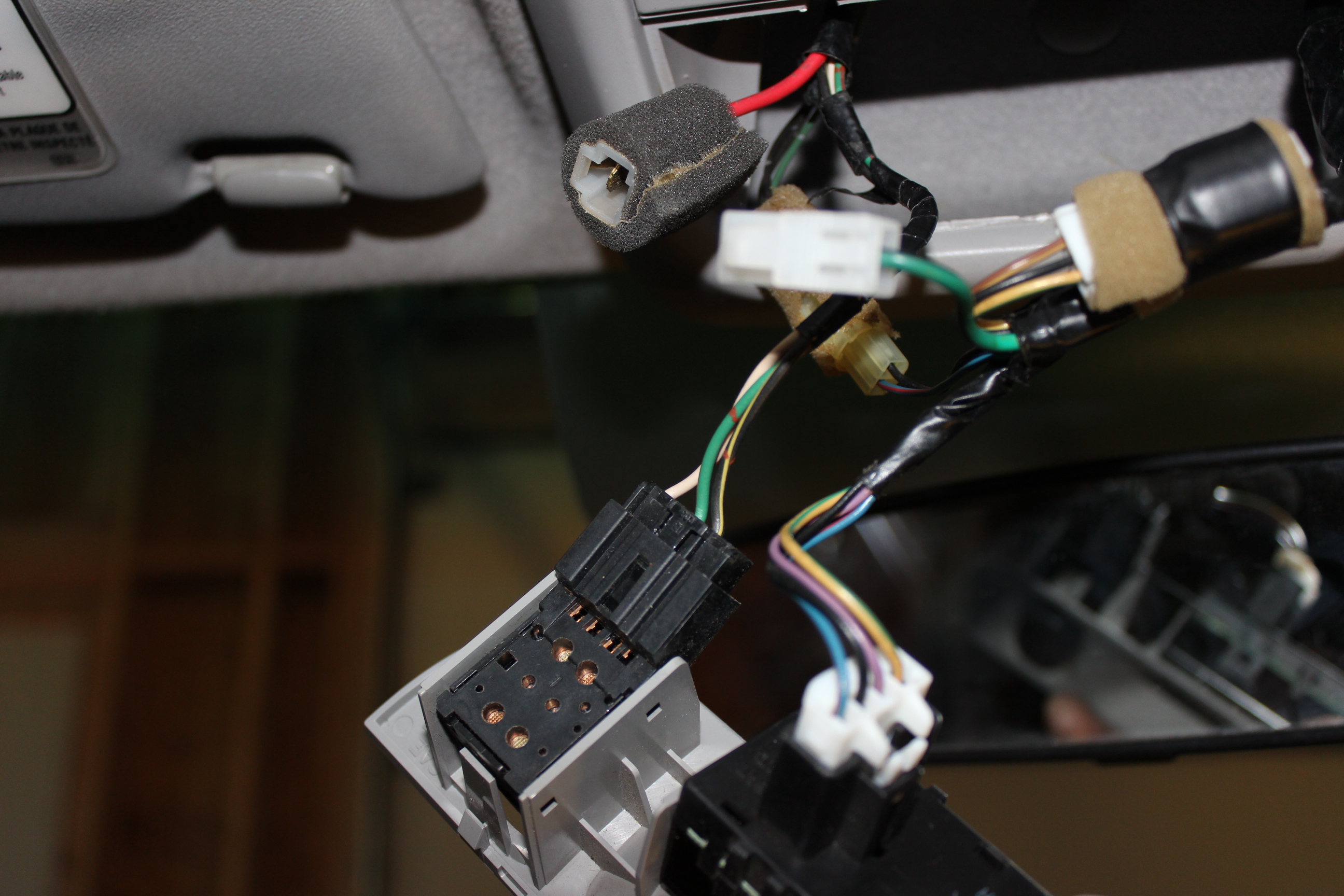
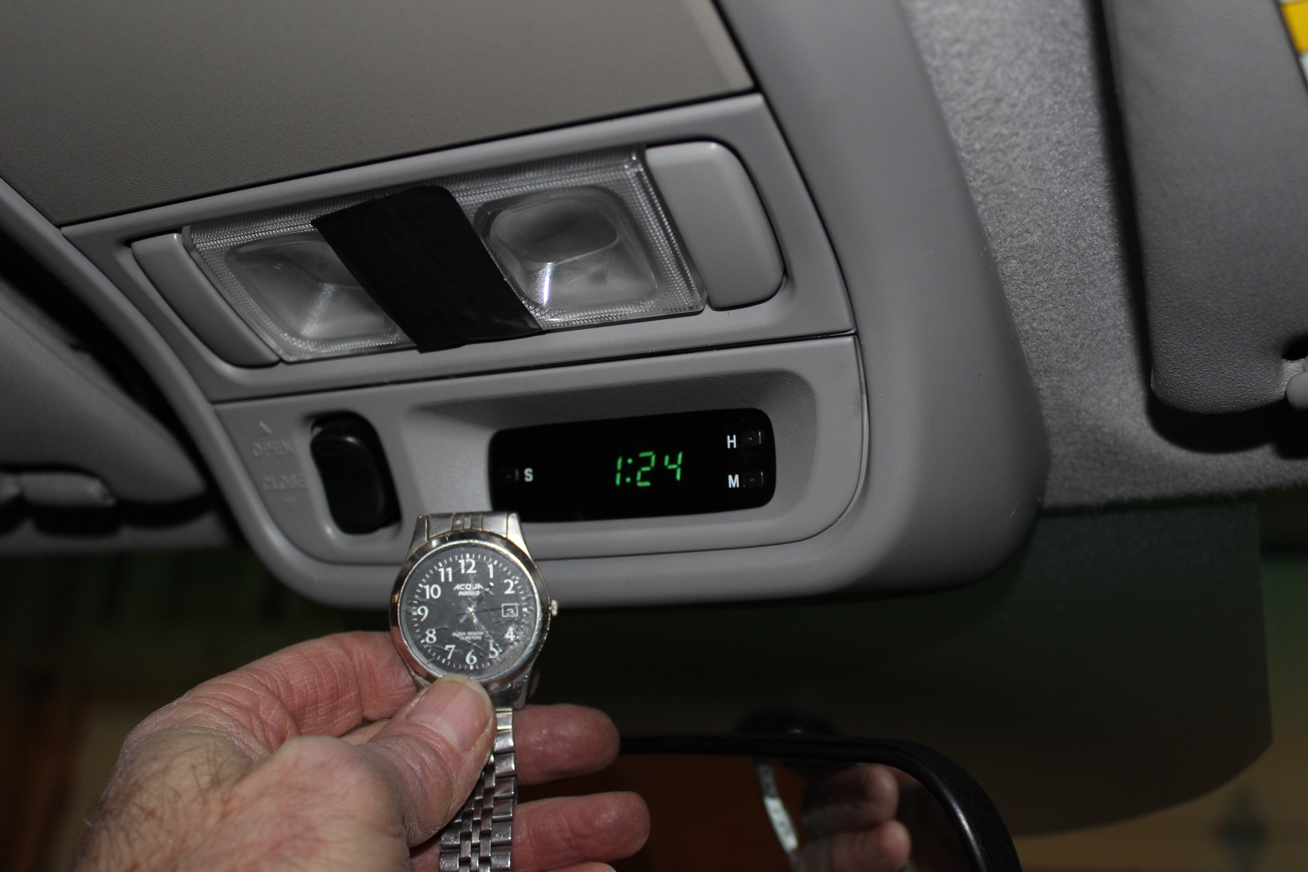
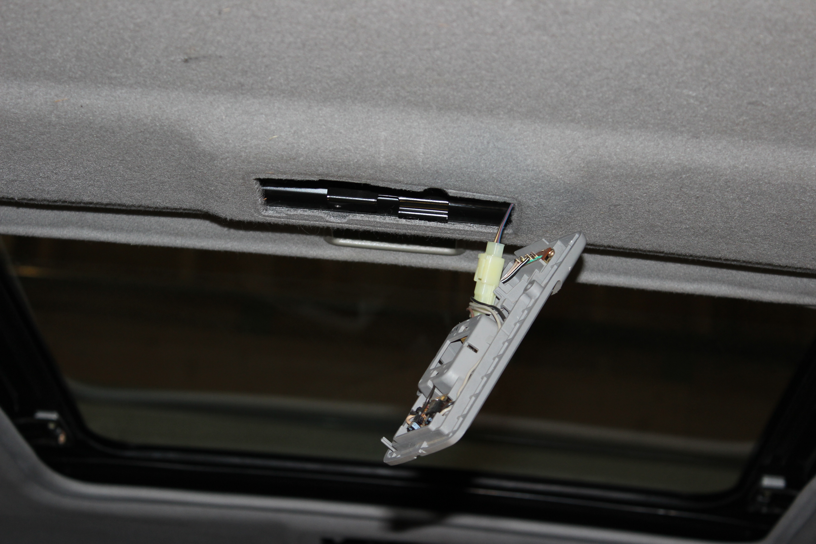
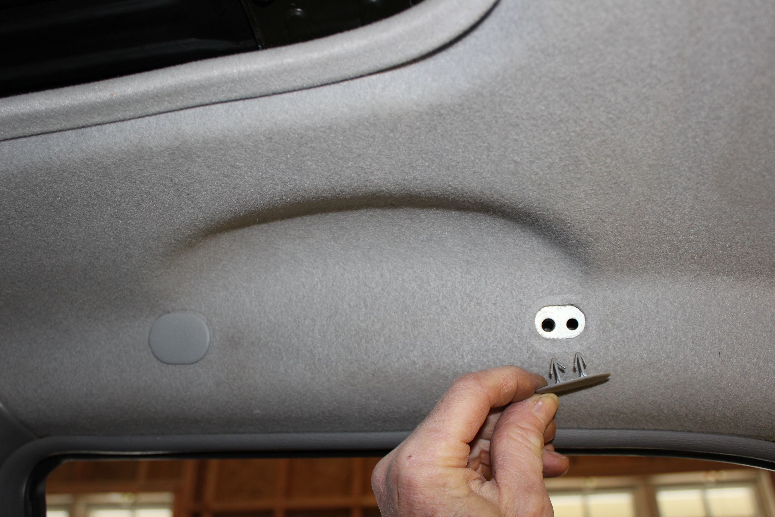
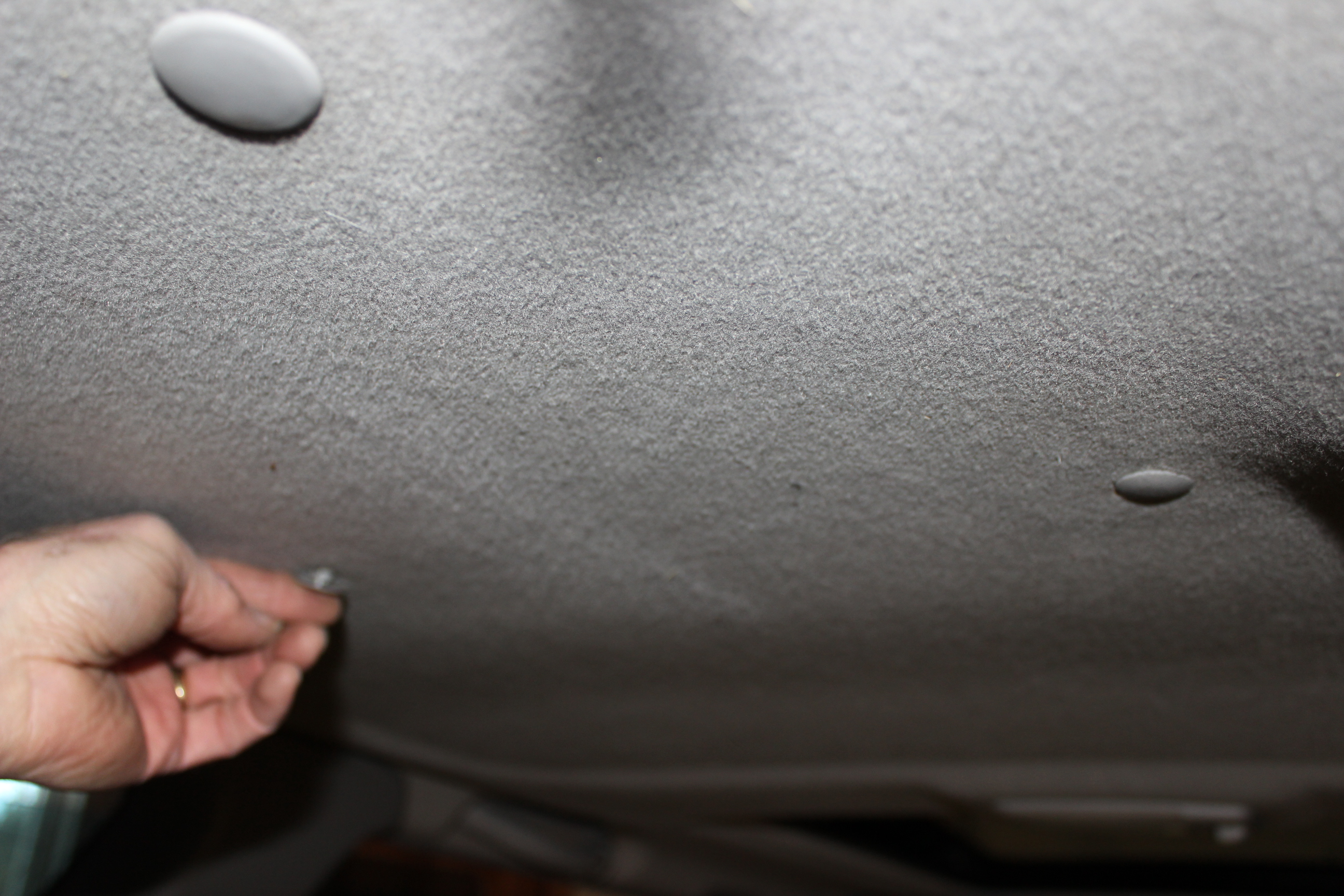
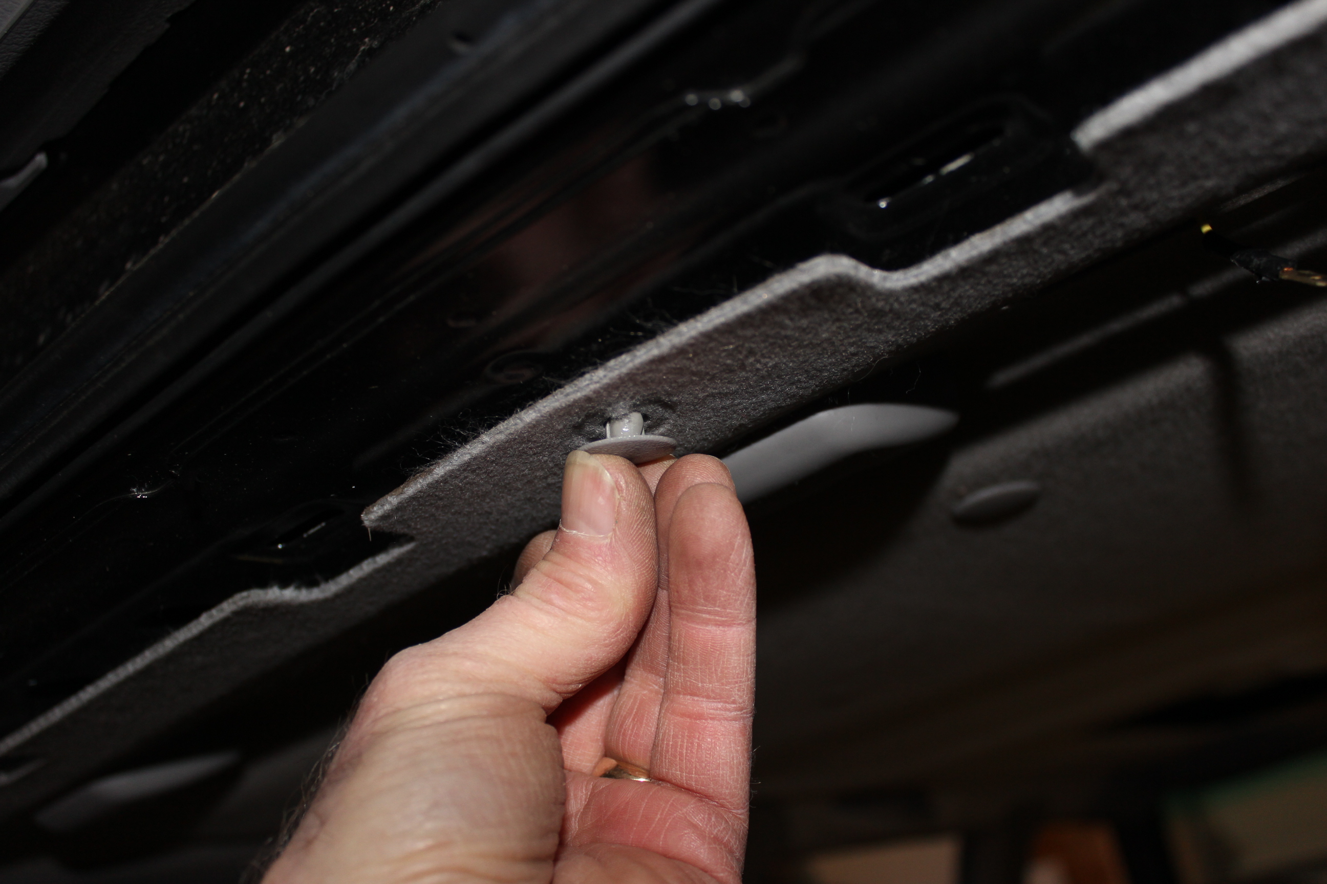
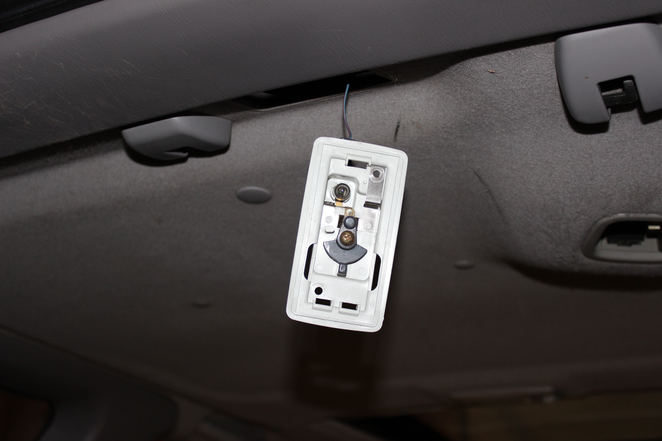
OK, a tricky bit here. For the overhead consol there is a plastic snap fitting. On removal you use a flat blade screwdriver and rotate it and it pops out. For install you need to spread the clips, push the square part through the consol hole, rotate it and then compress the clips back so they hold it in place. From the front you can see that the square bit with the screwdriver slot is now at an angle and holding the clip and consol together. In the roof there is a square hole, the clip will snap into. FIRST THOUGH, thread the sunroof wires through the rectangular hole in the consol piece where the other wires are running, this lets them hang out and not be pinched up to the roof. Snap the clip into the square hole, then attach with the three screws. Sorry for the fuzzy picture of attaching the front screws, the auto focus chose the wrong thing. The last is a gray plastic clip pin that attaches the headliner to the roof. Slip the sunroof cable onto the switch, but note here that I did NOT attach the large power connectors. I am not going to actually use the power roof any more, I don't trust it. Last, connect up the power to the clock and set it. I bet you are envious of my power broker time piece that my high-flying affluent luthier lifestyle affords me, eh!?
Back sides, rear seat belts, roof buttons, don't forget the center one in the back. Center top back piece, might have been better to put it on before the sides as they overlap it. I just slipped in under the side pieces and then snapped it in. NOTE: the metal snaps on the side and top piece like to kind of shift out of place. Press them all the way on/in their holder pieces before snapping an assembly in place.
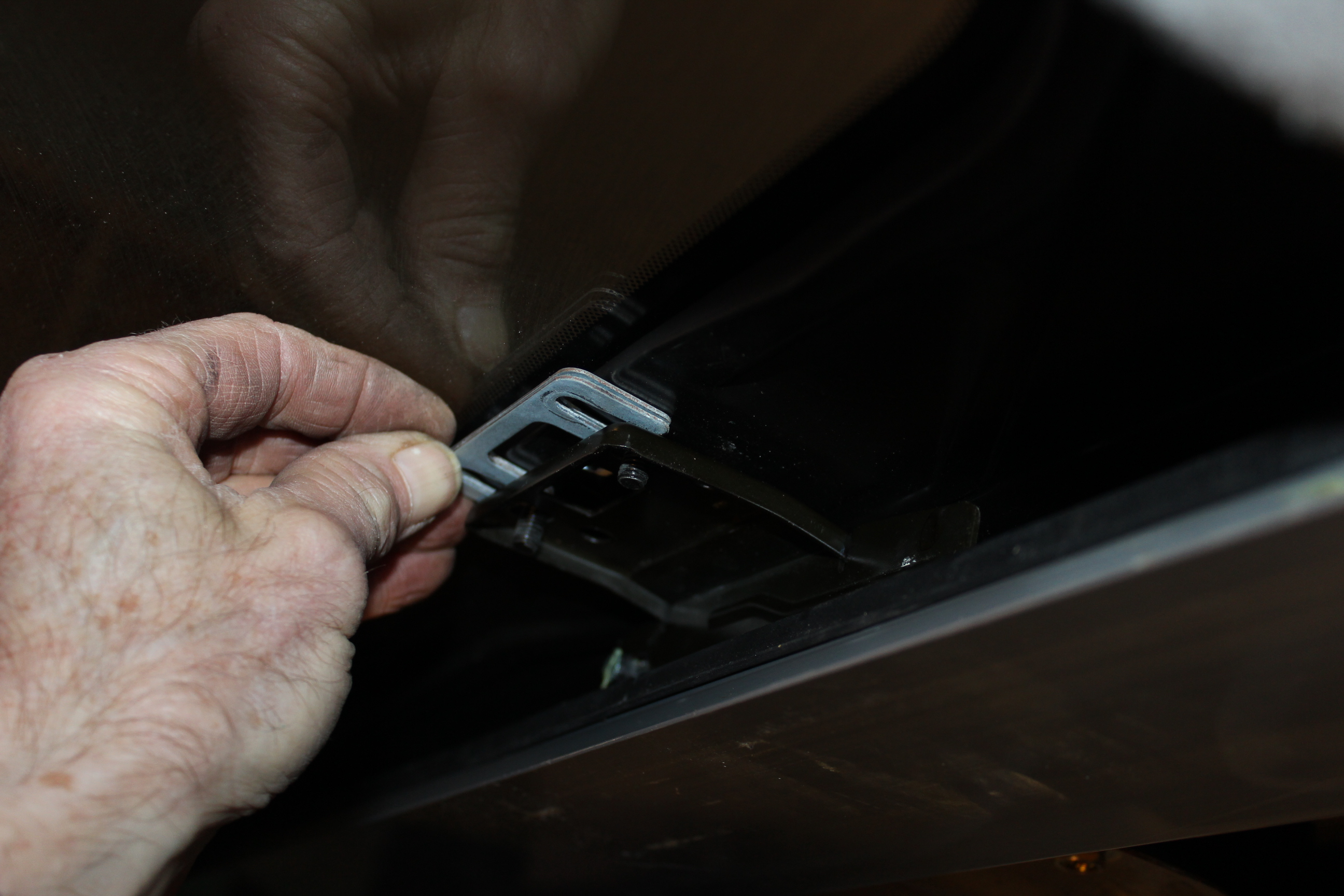
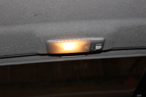
The last bits. Rear light and test, rear shock tower covers, and back up front for the post covers.
That pretty much completed the job for me. I don't trust the epoxy fix enough to actually use the power roof but I suppose it might be OK to use since I know the fix now.