© 2011 Alan Dunwell (Last Mod: 05/24/2011)
The following is a design for making a deflection jig used for testing mandolin plate. The original design was by Don MacRostie and published in the Summer 2008 edition of .American Luthier. This is my take on that design with a few modification.
All images may be seen in greater detail by double-clicking to get the full resolution images.
Basic Concept:
Almost all of my jigs and templates and such start our using rough materials with the idea that once I refine the design I'll make it up using birch ply and varnish it and brand it with my logo, etc. Somehow all that later stuff never happens, I end up with iteration number eleven-D2 that works really well, and then I use it forever. The second aspect is to keep costs low, often using scrap from dumpsters and whatever is at hand for those initial designs. One hopes that others might start with better materials from the get go since the design is pretty well finalized.
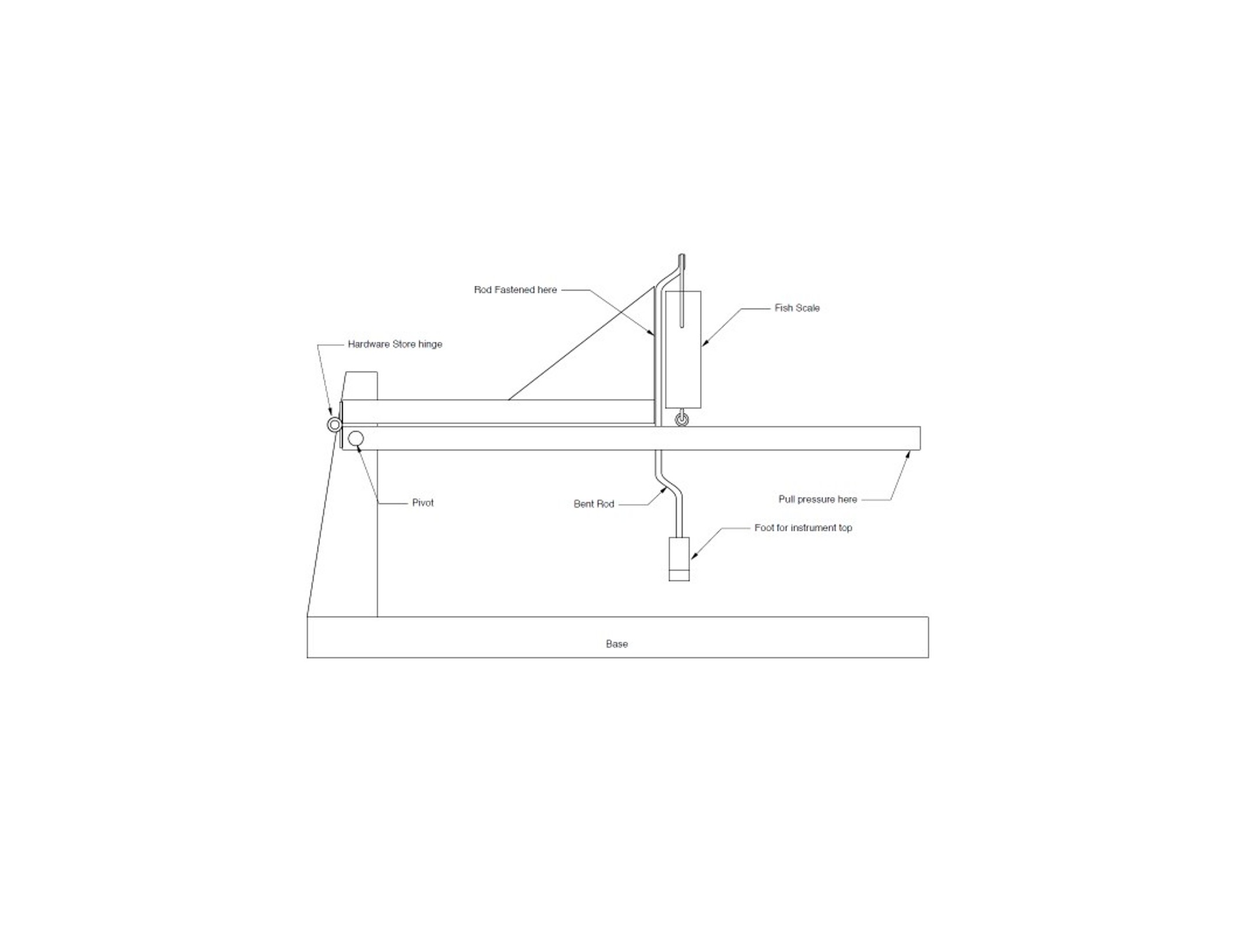
Here is Don's line drawing showing his jig design.
and further photos and discussion can be found in the AL article along with lots of comments and discussion with the audience at which he gave the presentation.
Note that he has the bent rod attached to the block on the upper lever. The lower lever is used to apply the downward pressure. I decided that I like a design with a single pivoting force bar with the rod and scale free-floating and the bottom of the scale only attached to the force bar.
I tend to be on the dumpster diver side of supplies for shop projects, but there are always some items that you need to purchase
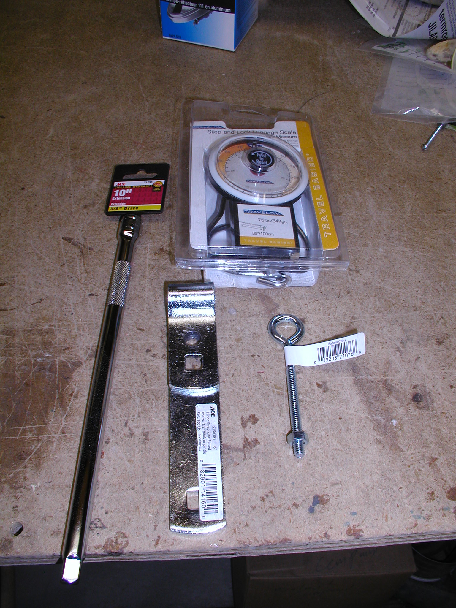
In this case I chose to have a straight through force rod made from a 3/8" extension, a luggage scale, a gate hinge, and an eyebolt all from Ace Hdwr. Total cost ~$us35.00 or so. Using the extension makes it easy to attach or detach the Pseudo-Bridge (hereafter PB) as needed. Get one that does not have a flair or shoulder at the male end. We want it to be able to pass through the guide block hole later w/o having to unscrew it from the hinge part.
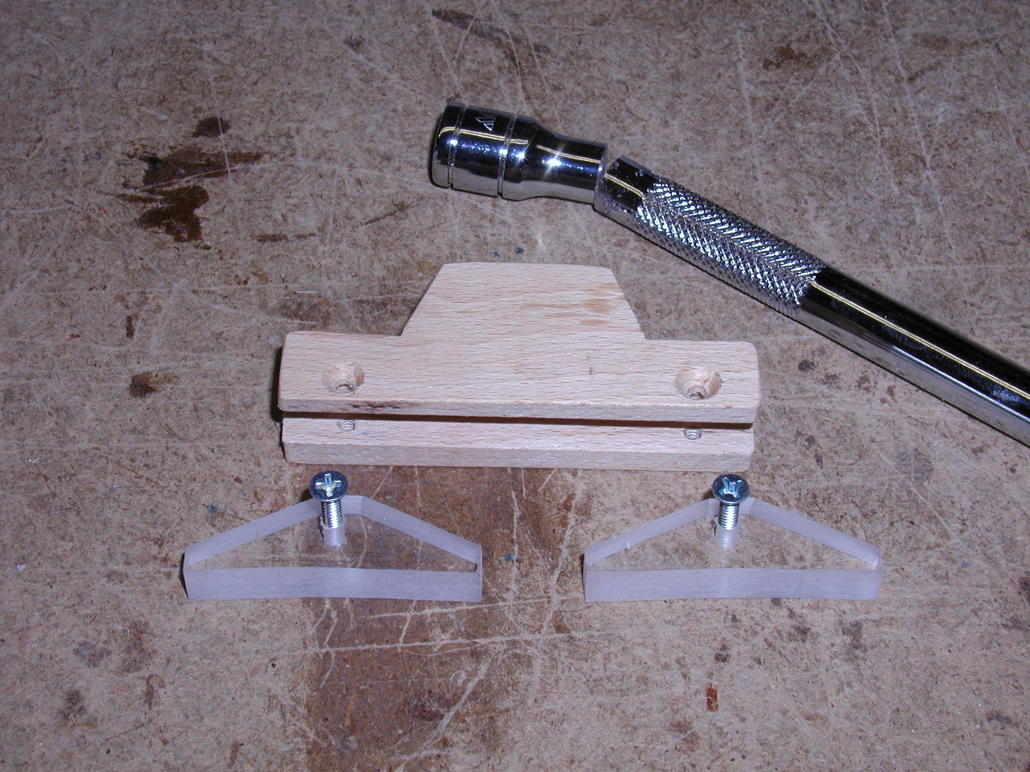
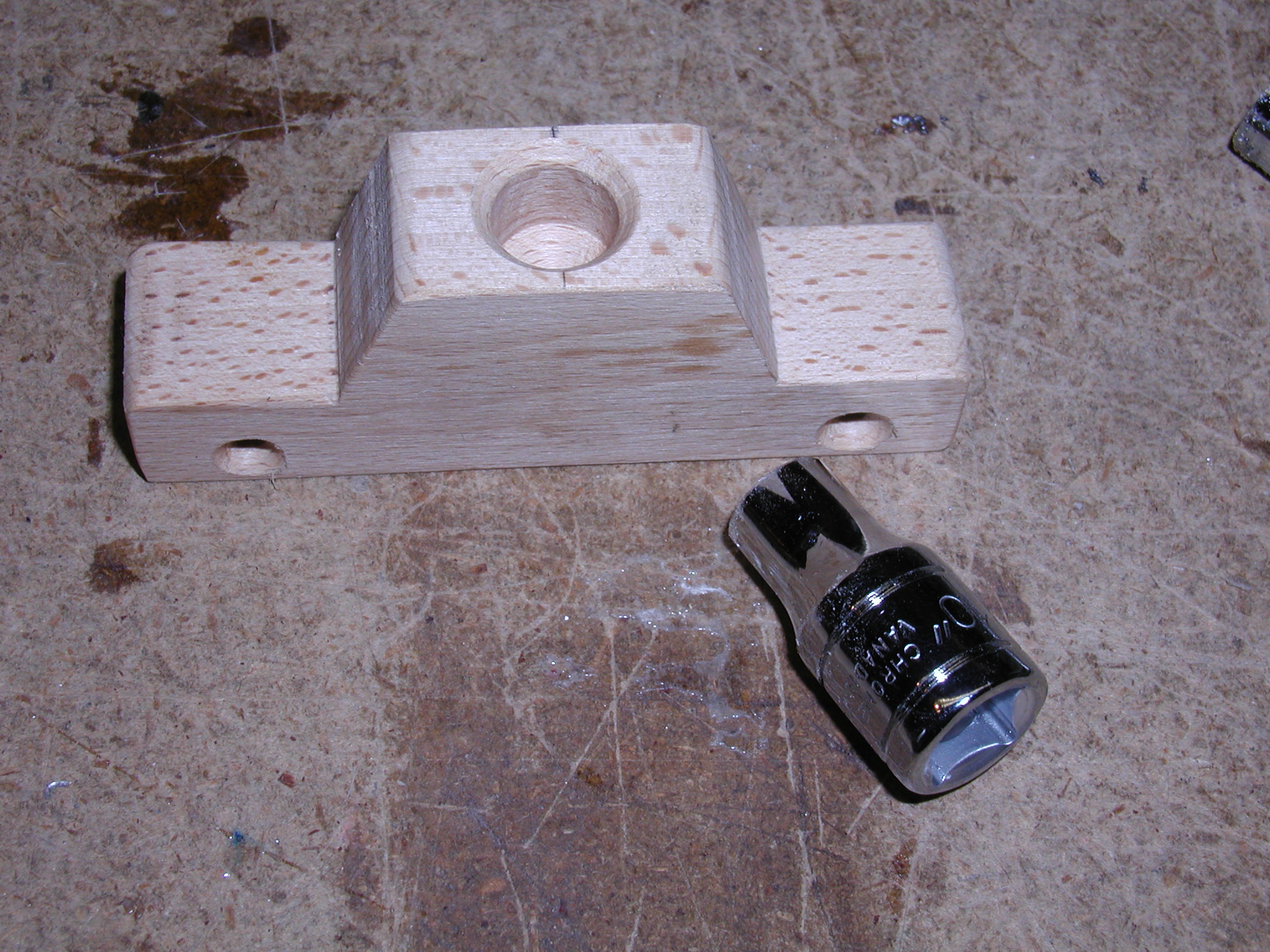
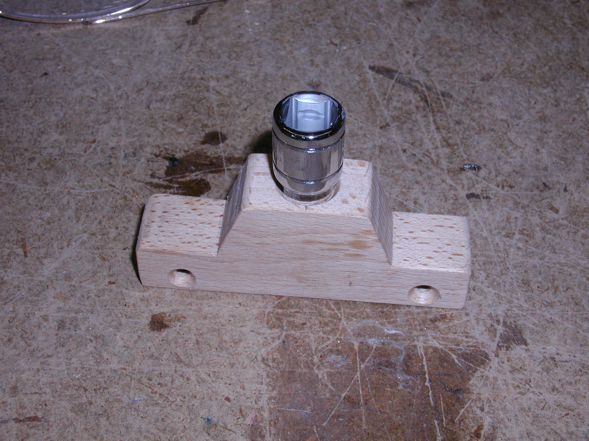
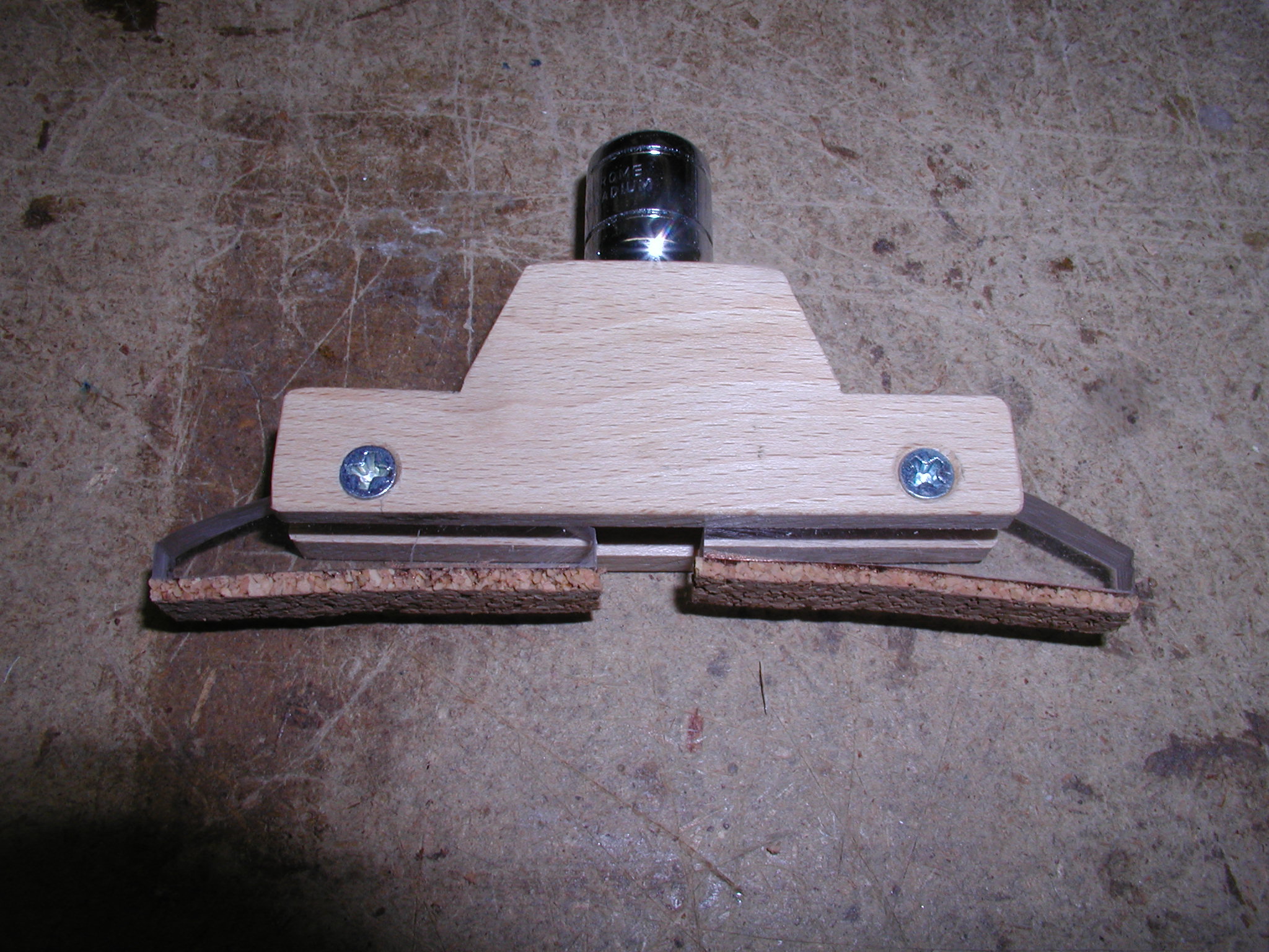
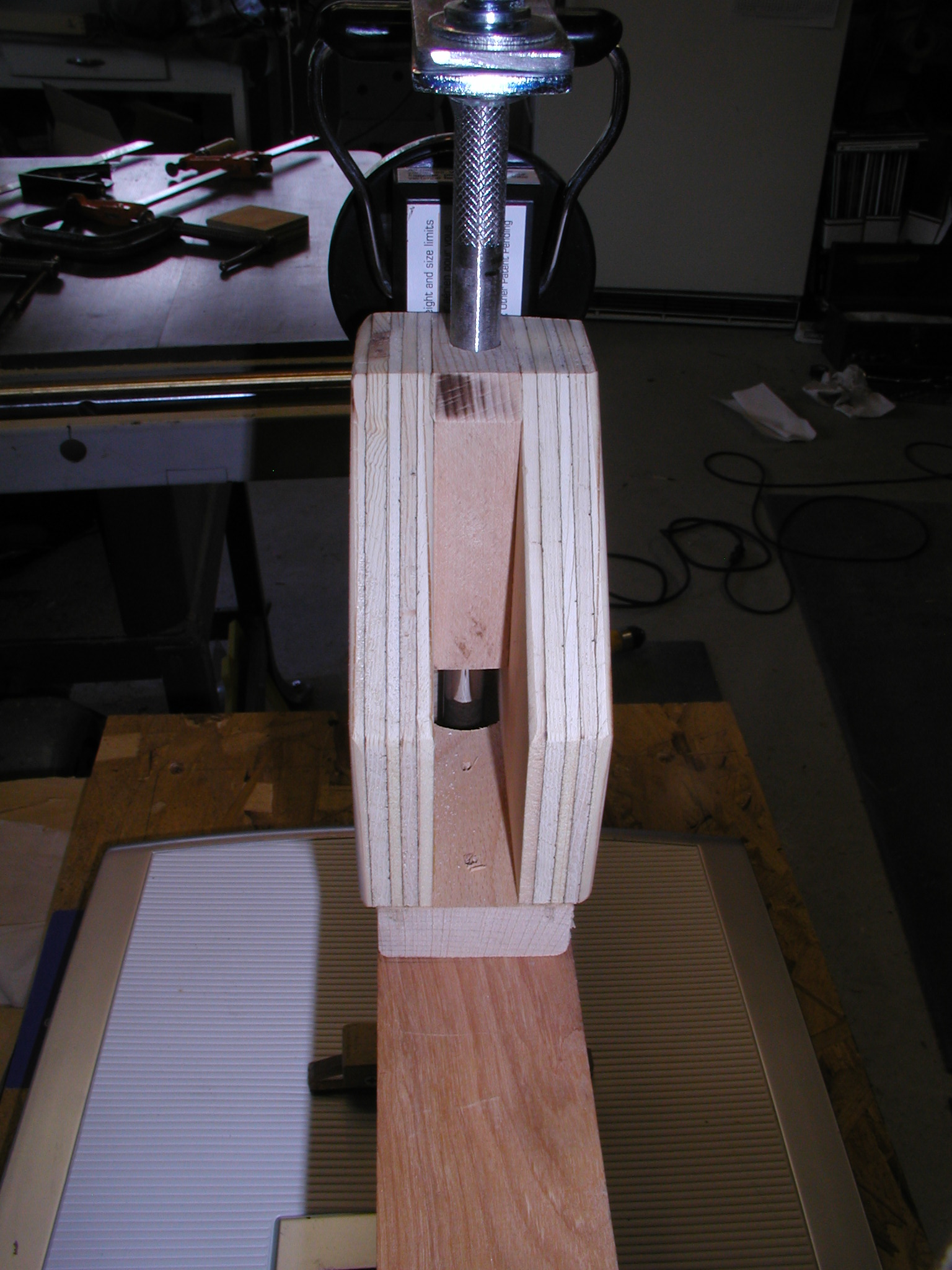
I cut the socket end off the rod to be used as part of the PB. The PB itself was made from some scrap maple and the feet out of some plexi-glass the same size as a standard Gibson-esque bridge. Note here that I made the wood part too short horizontally. You will see later that I didn't leave enough room for the dial gauges to clear the force rod, so although the foot pivots are in the right place the wood could have been longer. The maple is drilled and tapped for the screws with a force fit so no nuts are needed. The hole for the socket is just deep enough that it bottoms out with a force fit. I also added a couple drops of CA glue to the joint to keep it in place. Finally, I attached some thick cork gasket material to the bottom of the feet to complete the PB.
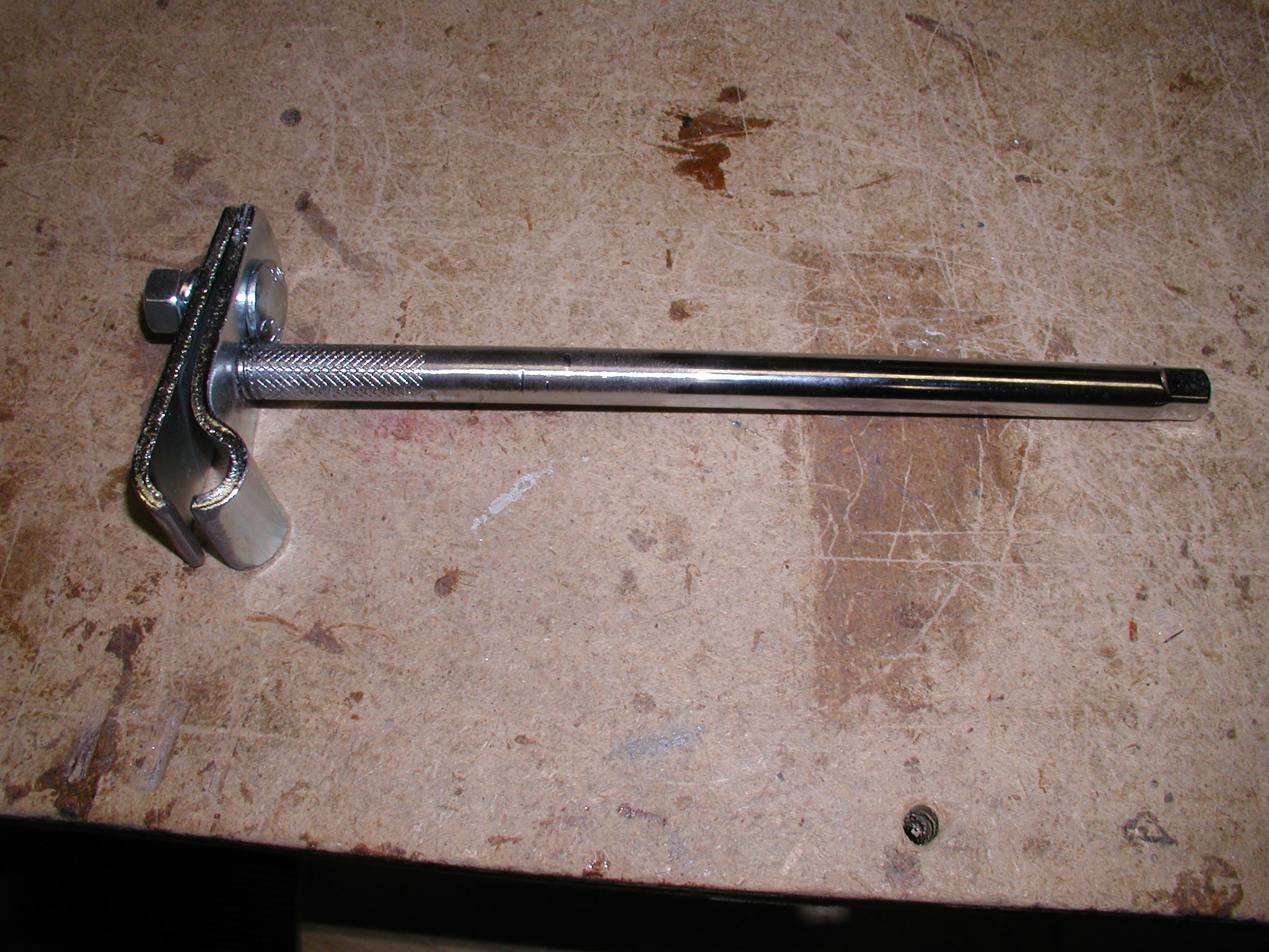
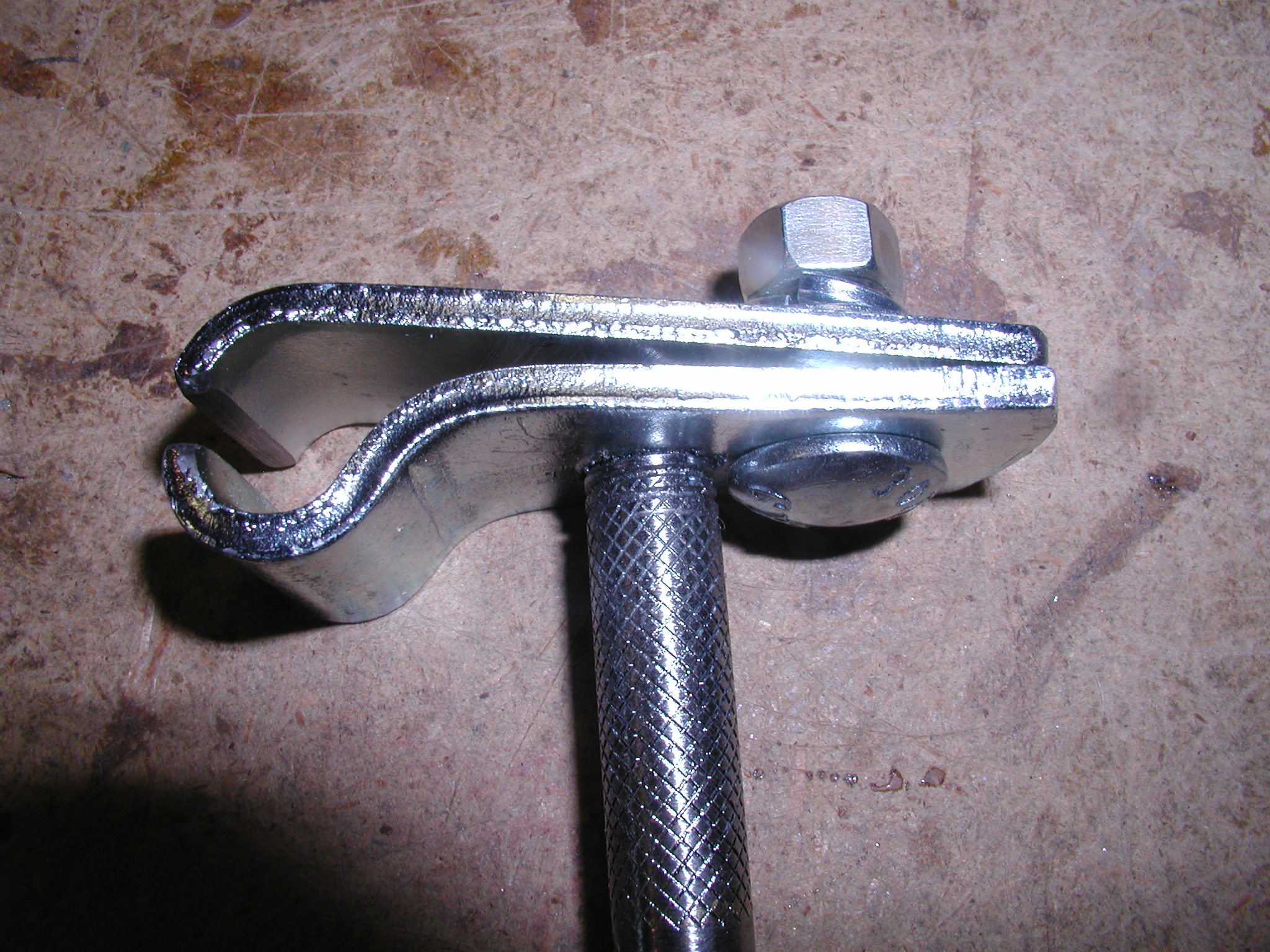
The force rod itself I then threaded at the cut off end with a 1/2"x13 die. Unfortunately, the selection at Ace was limited so this rod has knurling on it for a better grip with a greasy hand. This doesn't apply for our application so I hit it on the belt sander and smoothed off all the knurling. The gate hinge got cut short and the hinge pin end got cut to make it into two pieces. The bottom piece was also threaded with a tap and screwed onto the rod. I made the threads on both a bit incomplete so they are a force fit so, again no nut is needed and the orientation of the rod where it meets the PB can be adjusted easily by just moving the hinge position on the rod a bit. The carriage bolt at the back acts as a clamping bolt but I found I only needed to finger tighten it.This is used to hang the scale handle a the top.
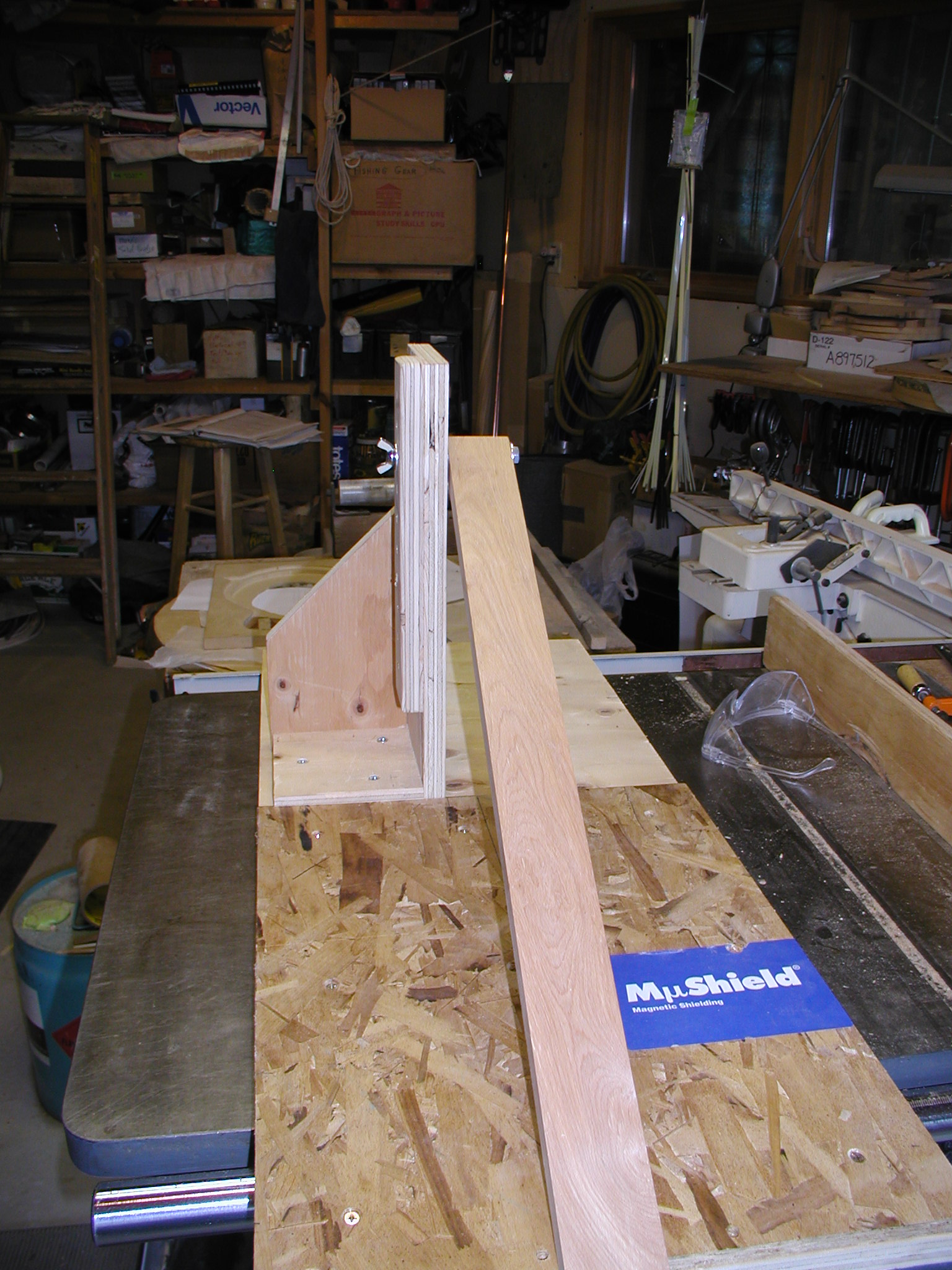
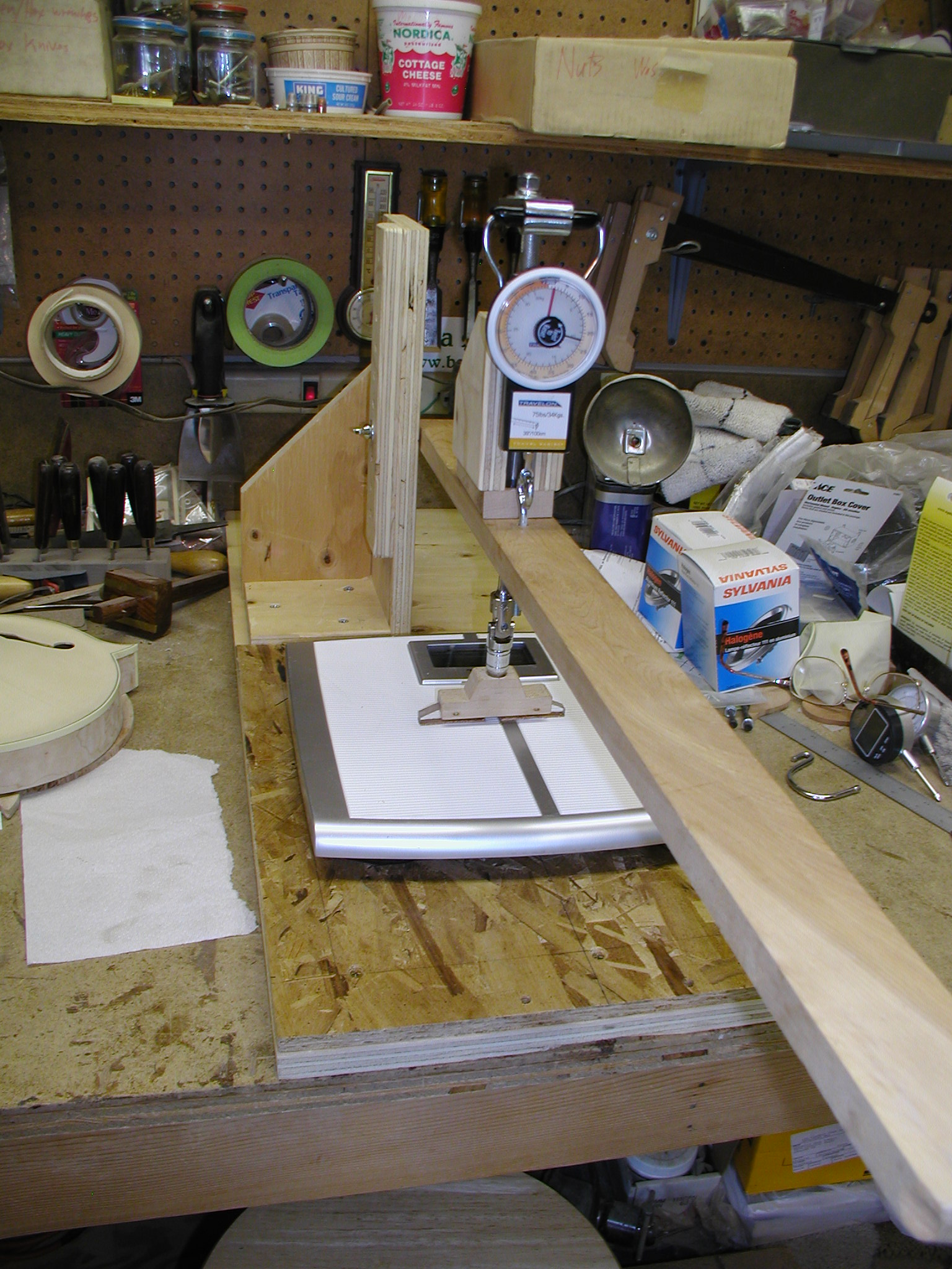
Don made his whole rig to bolt permanently to a work bench. I am more "space challenged" in my shop so I need to have the various jigs attach to the bench and then later break down and get hung in the rafters or go on a shelf. The plywood I used came from an old laser shipping crate, so it even has mu shielding!
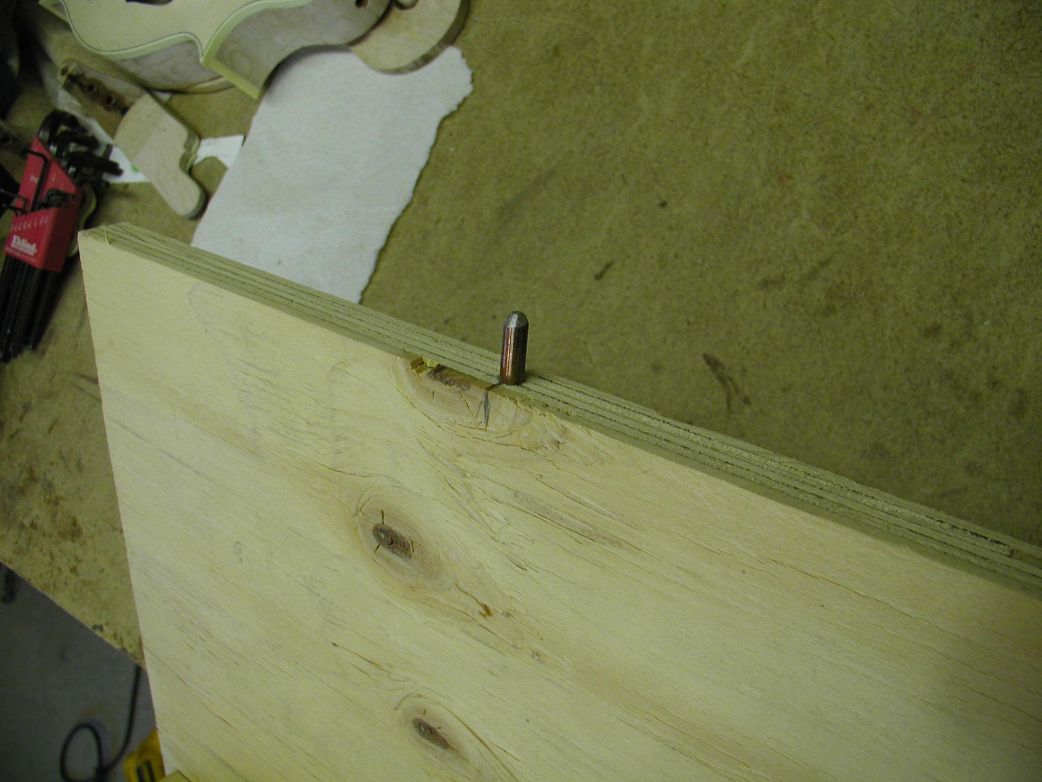
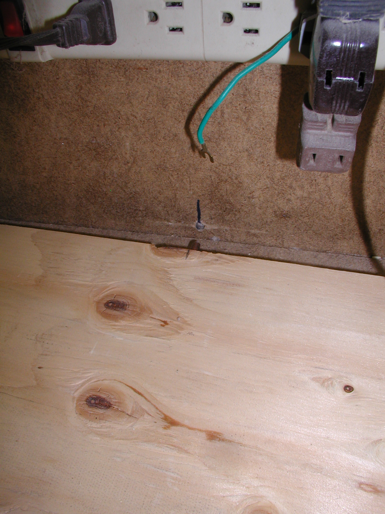
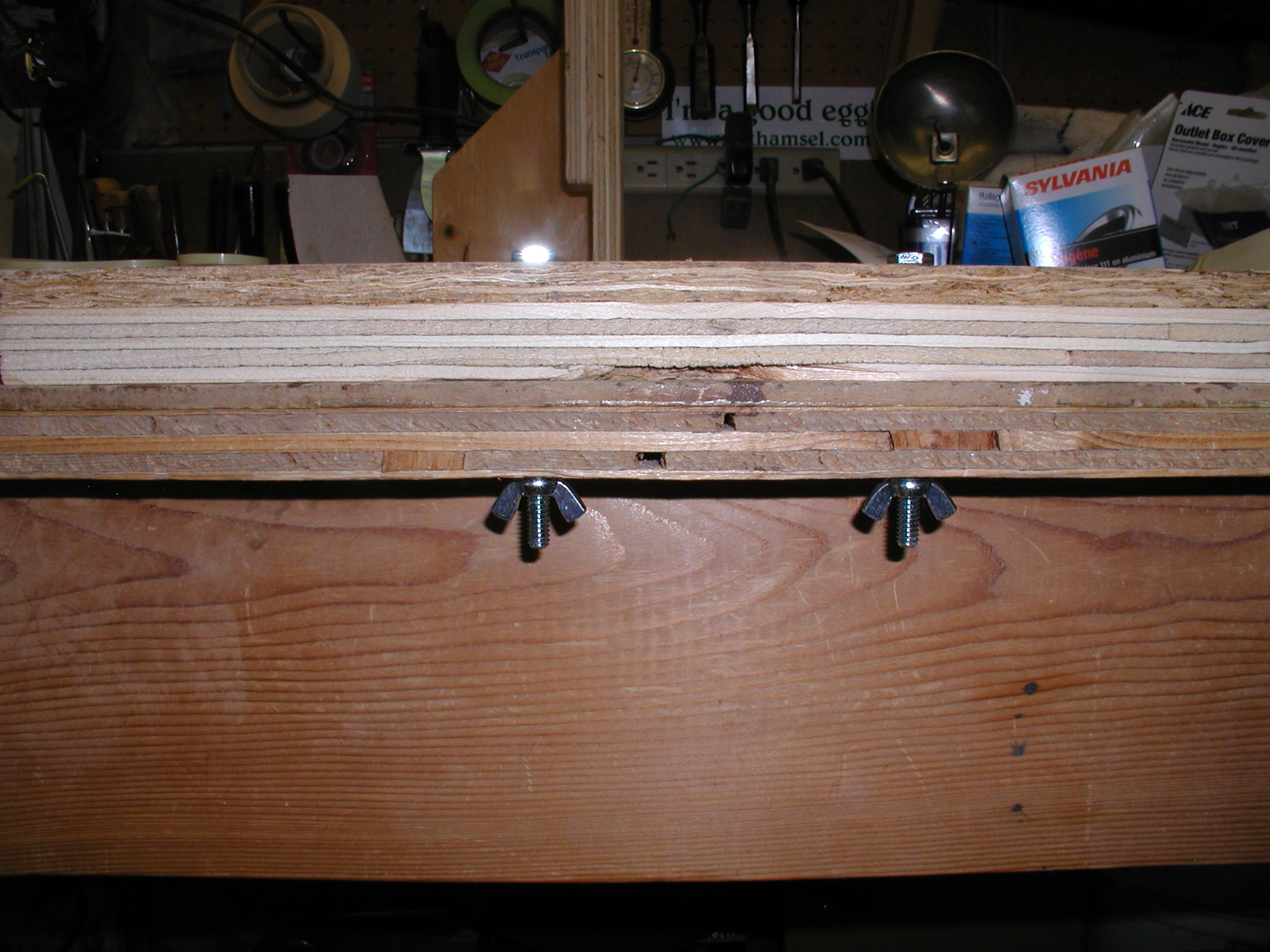
I have multiple jigs that attach the same way. At the back of my workbench is a 1/4"hole in the upright part. The jigs get a 1/4" pin that then plugs into the hole. The front of the jig is held on by a couple bolts through the front of the bench with wing nuts. Easy to attach and remove. For example my buffer is attached the same way and latter hoisted up in the rafters with a small block and tackle.
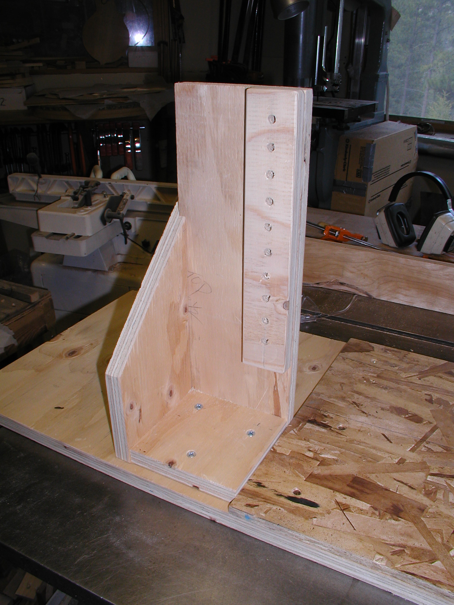
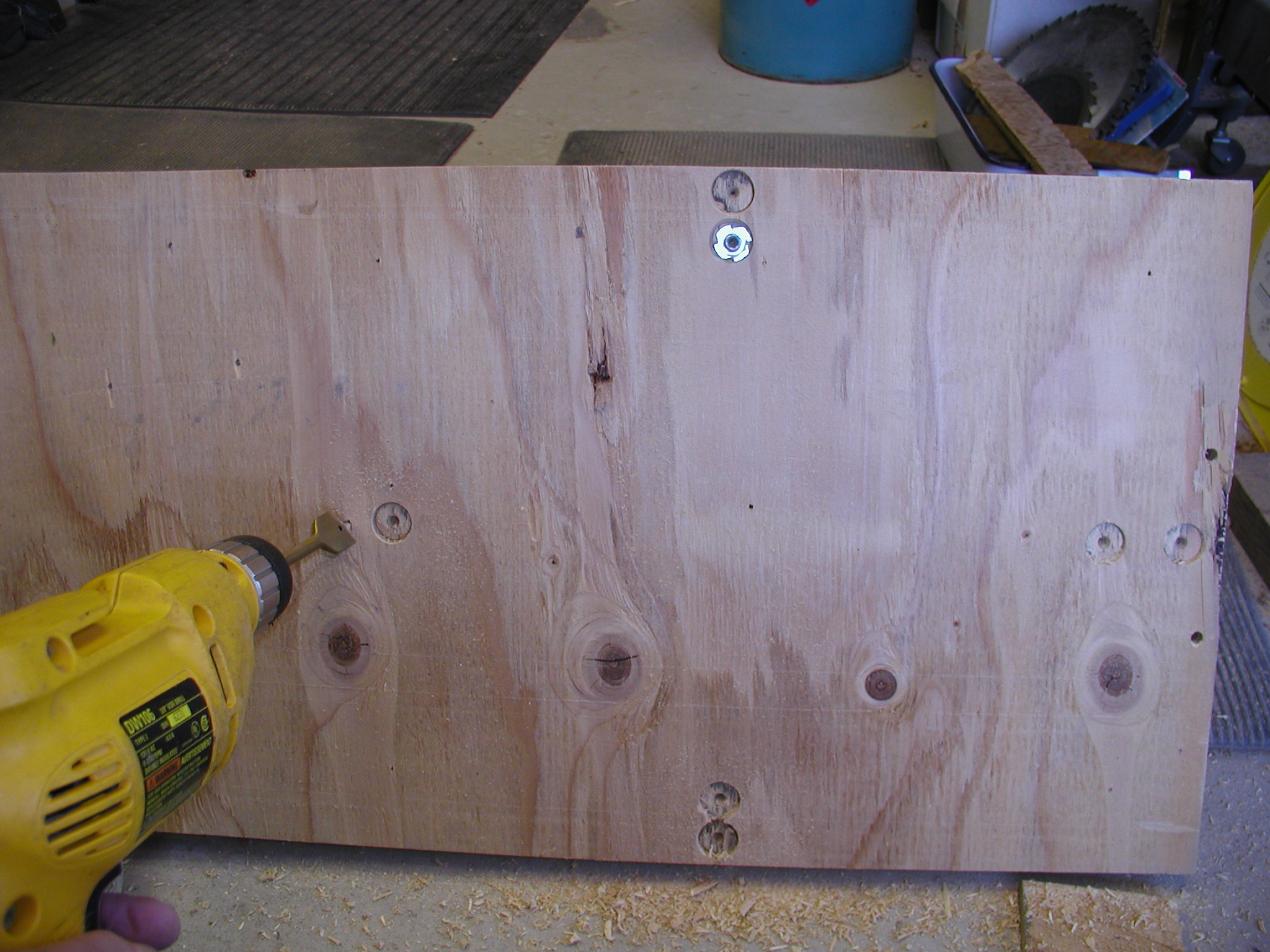

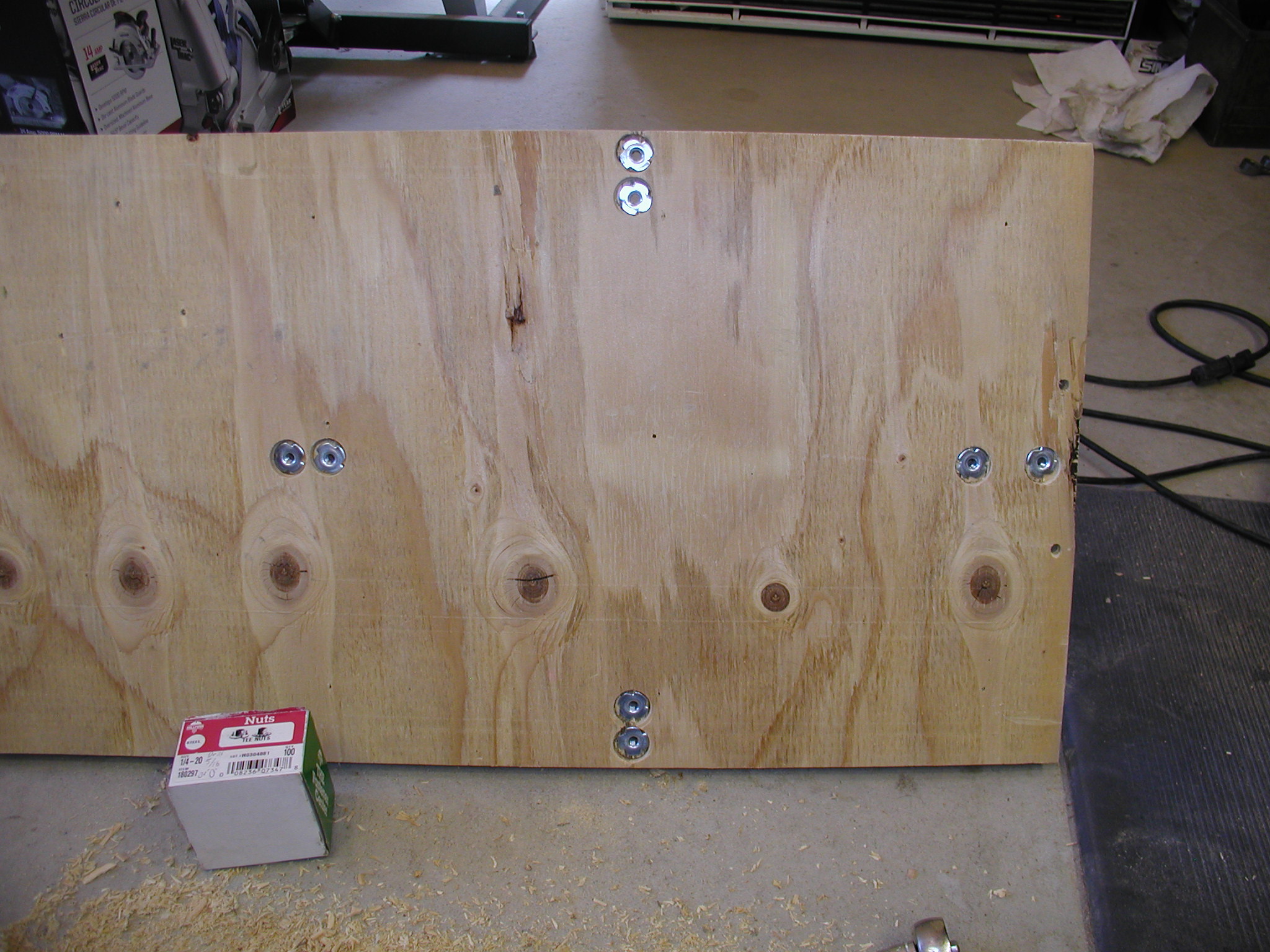
I made the upright anchor for the force arm pivot with multiple holes. I want to use this for plates that are attached to the ribs as well as for free plates and I may want to use it for guitars as well as mandolin family instruments. The multiple holes along the upright allows that. Note that that whole assembly can be removed with three screws or can repositioned later if I need for guitars. In order to easily hold the instrument parts to the base board I put in blind nuts (T-Nuts). These are positioned for the mandolin but I can add more later for guitars and bouzouki as needed.
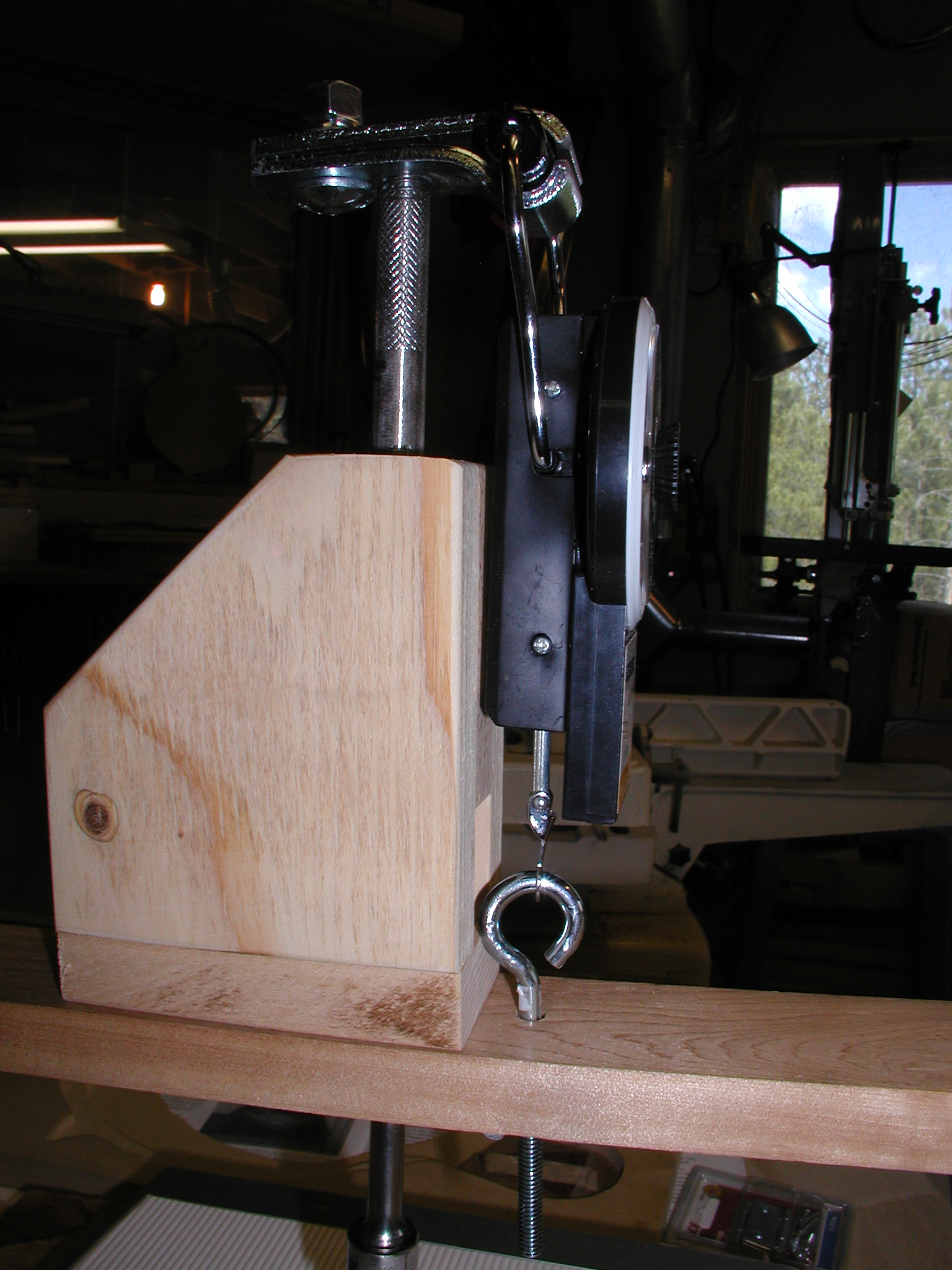
The arm is a piece of maple that I got free from a local lumber yard's "rippings pile", the edge and off cuts as they square up the rough sawn board. The pivot end has a 3/8" bolt though it. The bolt can be passed through any of the holes in the upright and the wing nut snugged up and it still pivots well. For the scale attachment and guide for the force rod I made a silhouette type box since it is just acting as a guide and doesn't bear weight. The rod is passed though a hole in the block and both the rod and block are waxed with regular old Johnson's paste wax to make it slip easily. Here you can see that the scale is free-floating. It's handle is attached to the hinge piece of the force rod and the bottom is attached to the arm via the eyebolt. Note that the drawback here is that the line of force is not exactly in line with the scale. Given the rigidity of the parts I didn't worry about that since I don't think there will be any flex or deviation due to the lever arm of the hinge piece.


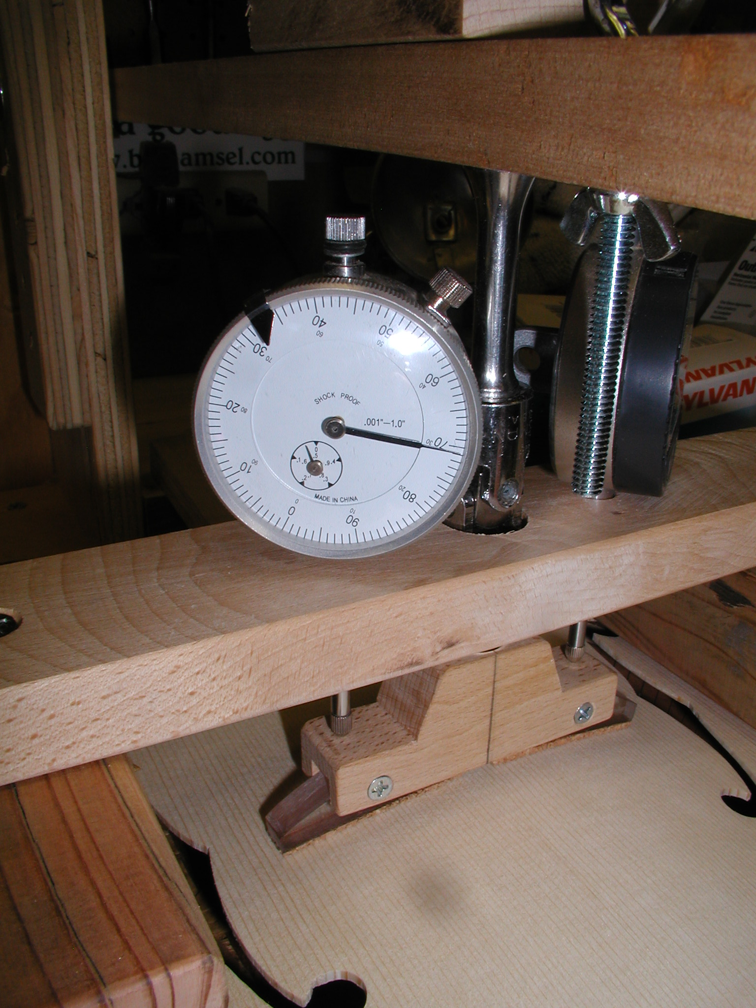
In order to read the deflection we need some sort of rig to hold some dial gauges which will read the movement of the PB. Using more scrap maple I made the cross piece with a central hole to allow access for the force rod and U-joint assembly. Outside of that on each side is a hole for the dial gauges. These just are a snug press fit so it is easy to adjust them up and down to mate with the top of the bridge. The side blocks are some scrap redwood decking 2x4 off-cuts that I resized to accommodate the height of the mandolin plates. They are attached with a single screw each so they can be angled as needed to rest on the binding/rib area. Last of all there are a couple screws on the end that the springs from the base board attach to. The springs were some random springs that I got at our local "Resource" recycle supply yard but I've seen similar at Ace.
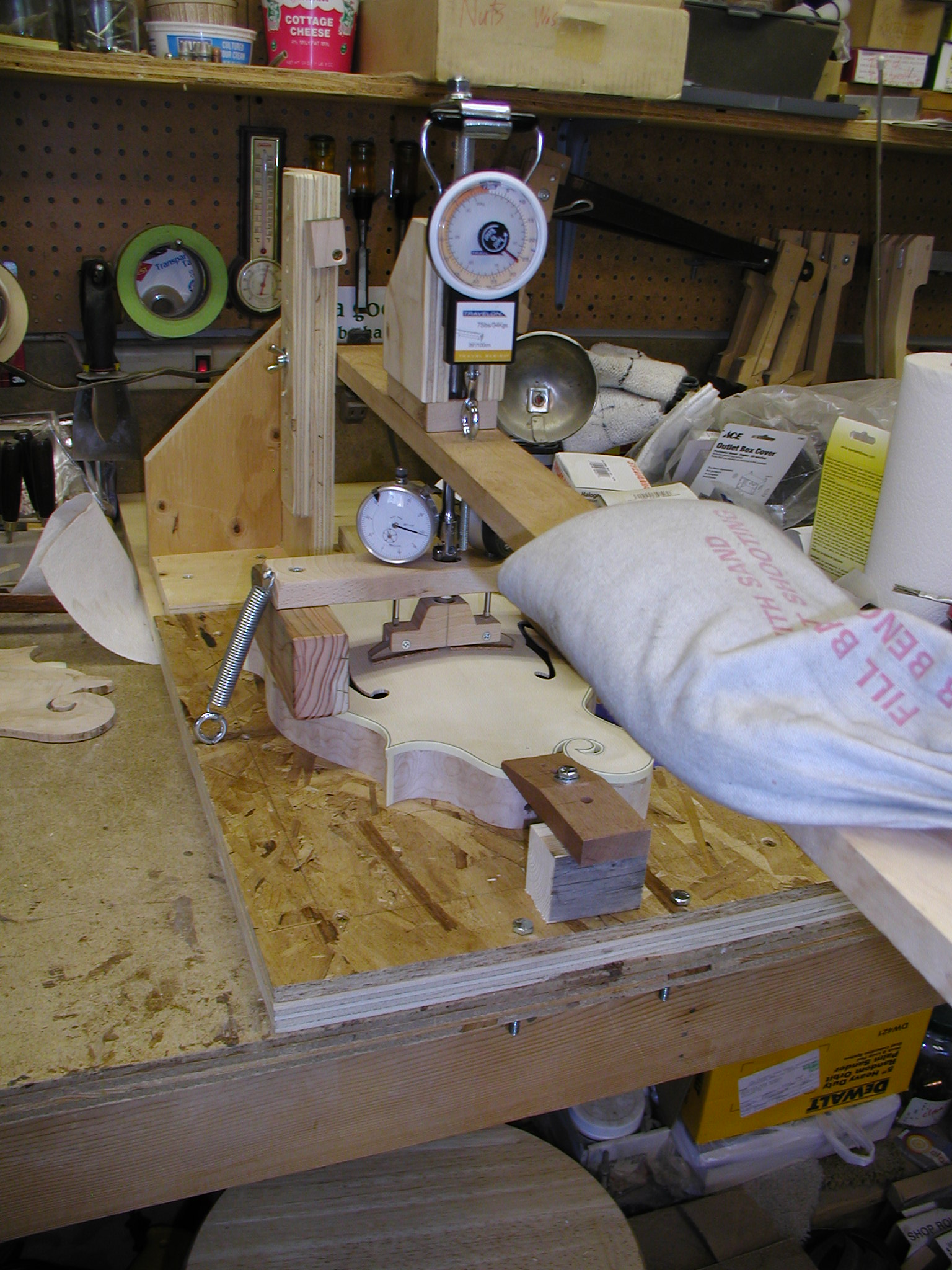
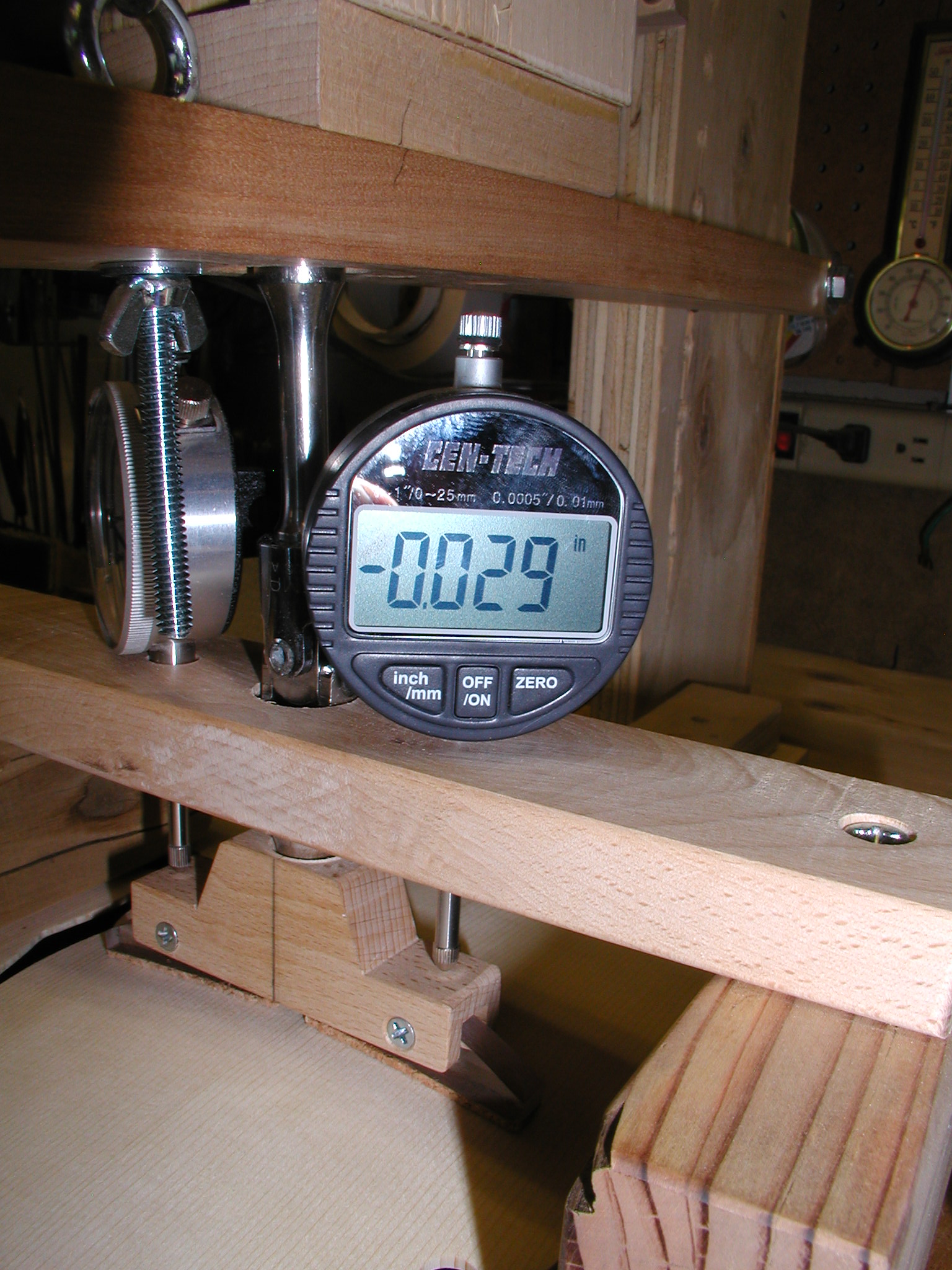
Oh skeptic that I am, I didn't trust the scale. So I compared it to a digital foot scale, which I also didn't trust. So I first tested the foot scale with a 25lb bag of shot and noted that the scale said 23.5lbs. Then I applied force with the jig till the foot scale again read 23.5lbs and noted that the luggage scale read 27lbs. Ahhh, love them high precision instruments. Here I am testing a mandolin top that is attached to the ribs. I diddled around and positioned the top assembly till it was directly under the PB and held it down with some clamps at the head and tail block areas. These are like machinists clamps with a block at the back, an arm that does the clamping and a bolt through he arm to the blind nuts in the baseboard. I then spring clamped the dial gauge assembly in place. The springs are strong enough that it acts as the clamping for that area, no additional clamps were needed there, it only needs enough clamping to keep the ribs from spreading. Notice how I have to have the dial gauges turned sideways a bit. This is what I was talking about earlier where I didn't make the PB wide enough and the dial gauges interfered with the force rod. I found that trying to hold down the arm and read the scale and then read the gauges to be a bit problematic. But I found that a partial bag of shot on the arm did the trick. I just start with it in close and move it out on the arm till the scale reads 27lbs and it holds that pressure for me. Then I can read the gauges. I'm using a mix of gauges here since that is what I had in the shop, but I plan to get another digital gauge because it reads in both inches and mm. ~$us20.00 from Harbour Freight or Amazon.
An annoyance was the U-Joint thing. It "seemed like a good idea at the time" when I read that Don was doing this. But in practice it was a bother and kept trying to tip and rubbed against the dial gauge assembly. In the future I will just use another short extension to replace it and this will help in getting the PB centered true on the plate. Also notice that my eyebolt is way too long. I wanted it for adjustment in case I needed that but, again in practice, it was not needed. I will probably replace it with a shorter one.
Suggestion:
If you know other builders in your area, or if you have a guild or club, you may want to go together on this project and share the jig around. It really doesn't get used except for an hour or two at a specific place in the build process or for testing of completed instruments for comparison. I could loan this jig out to folks in the Colorado Luthiers group but I am in kind of a remote location to the rest of the folks, but for a more closely knit group this would work well. Since it is a bit of a bother to hand it around it makes sense to all get together and just make a party out of it, and it is a good excuse to have a Bar-B-Que later.
I hope this pictorial is of some use and again I credit Don for the clever original thought. I am just starting to use this (as of May 2011) and recording data so I don't yet know what the deflections mean in terms of getting the sound I like. Right now I'm still tap tuning and doing Chladni modes till I get it like I want, then recording the deflection as a data point. Later I hope to be able to turn this around and use the measurement to determine if I need to further carve or tune the plate. This is the same process I used when first starting to record Chladni mode data.
Enjoy and be well,
Alan Dunwell